|
In the Ranger and Valiant, the over heated 18K carbon resistor will eventually fail. With today's higher line voltages and aging equipment operated near its maximum ratings it is inevitable. Frequently it causes blown LV B+ fuses and smoke when left unattended to warm up the radio for an enjoyable session of AM. Very frustrating. If you have not yet done this, you should do it as a preventive measure.
You do not have to remove the front panel to fix this. In fact, I recommend that you do NOT remove the front panel, since there is a trick to avoid damaging the shaft coupling to the knob.
I have not seen anyone offer a photo tutorial to perform this repair. Once you have done this, it will be easy. Once you have seen how easy it is, you will try it for the first time with confidence.
Obtain a thin piece of wood to put under the transformer, to stabilize the radio while it is standing on end. Tipping over a radio and having it land in pieces on the concrete shop floor will positively wreck your day.
Remove the VR tubes and store them. Also remove the other miniature tubes in the exciter.
Carefully remove the screws on the access cover on the side of the VFO facing the VR tubes. This is the meter side in the Ranger. Do not loose the screws or star washers in the works of the radio. The Law of
Selective Gravitation (otherwise known as the “jelly bread rule”) dictates that a lost piece of hardware will fall in the spot most likely to cause damage when power is applied. Pilot lights and such as well as the side panel can now be gotten out of the way.
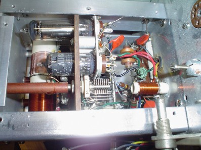
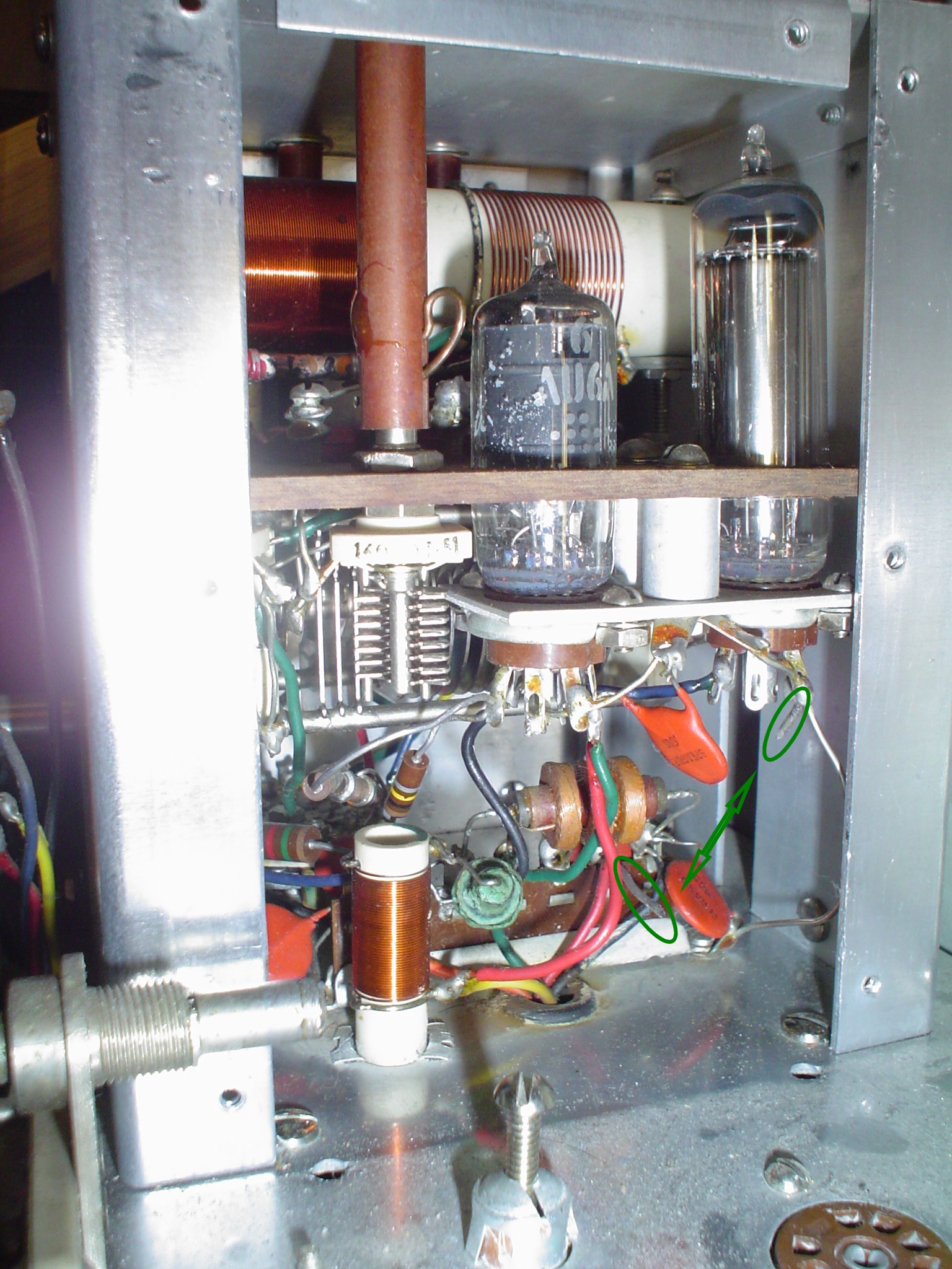
 Click on photos to see connections indicated.
The smoked 18K resistor will be evident. Clip the leads as close to the resistor as possible, avoiding loss of parts into the works of the radio. Horizontal normal position of the radio for this procedure is better than upending it. Attach wires to the the stumps of the 18K resistor you left when you removed it. Pass the wires through the grommet to below the chassis. I like teflon wire.
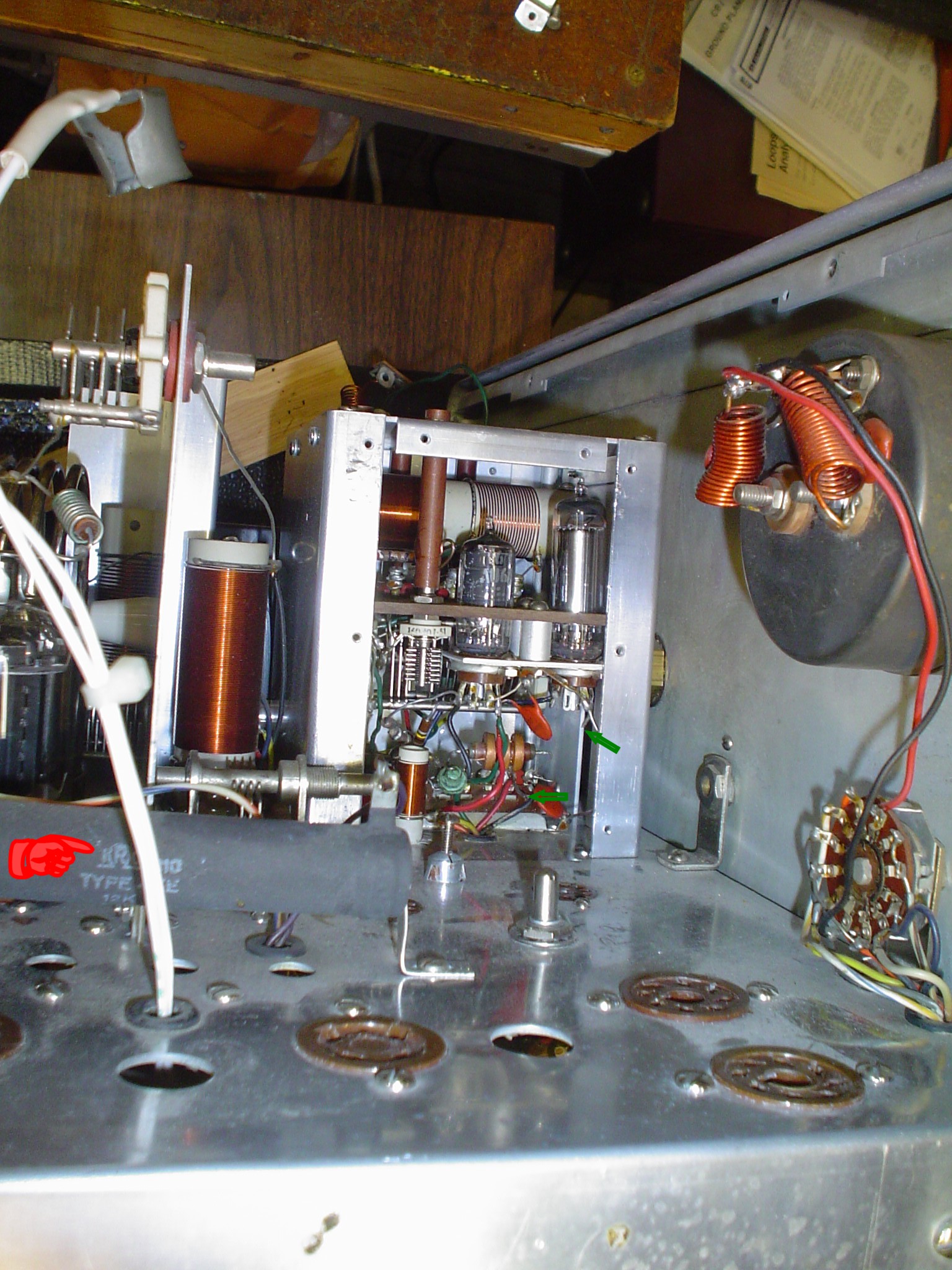
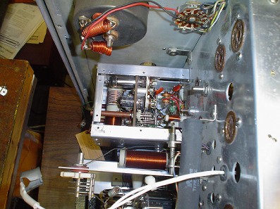
 Click on photo to see connections indicated.
Test the tubes and replace anything questionable at this point. The VR tube may be fried due to excess current. Carbon resistors often go DOWN in value when they are overheated.
Turn the radio upside down. Use pieces of wood to support the transformers to avoid damage to the tubes and plate coils.
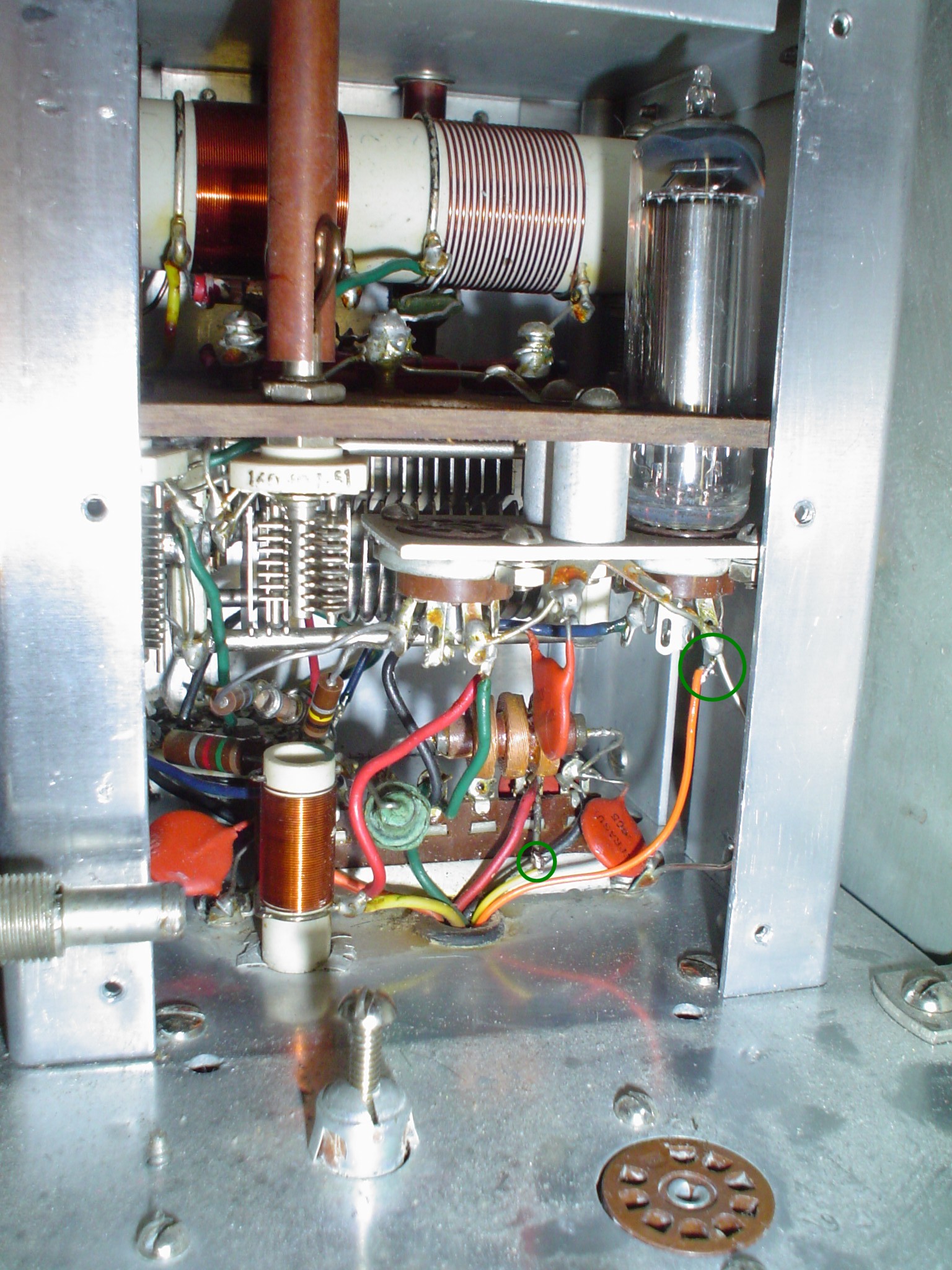
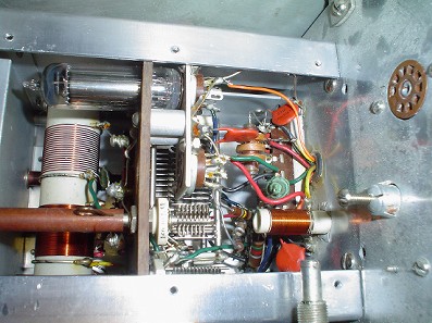
 Click on photo to see connections indicated.
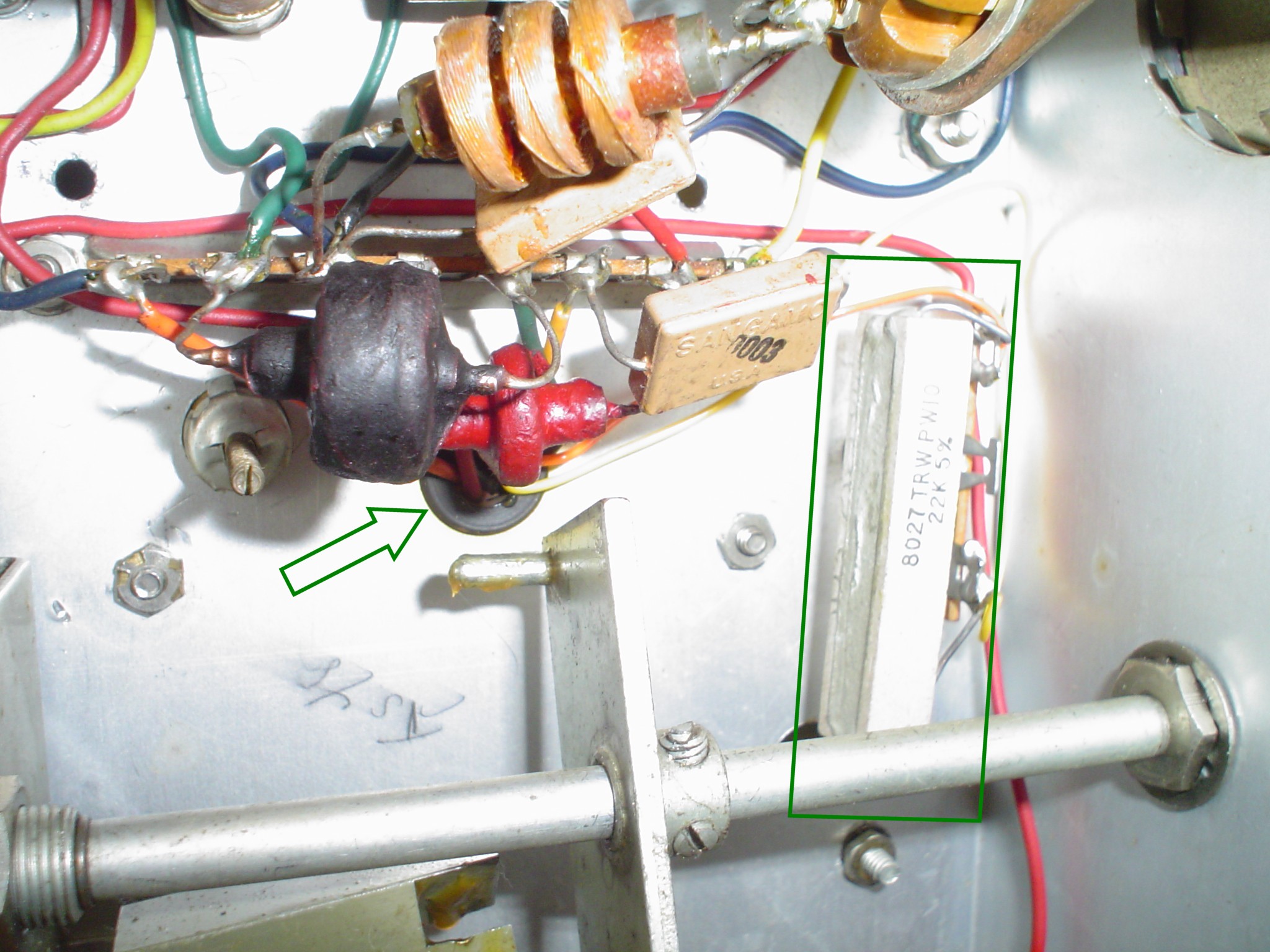
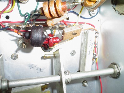
Mount a terminal strip and wire wound resistor as shown using the front two screws mounting the VFO assembly to the chassis. Attach the wires from inside the VFO previously routed through the grommet to the resistor.
Reassemble the VFO and rig. Recalibrate the VFO per the EFJ manual for the rig you have.
Before you reassemble the transmitter into the cabinet, there a three more VFO related items you must correct. This appies to the Valiant and the Ranger, or any other E. F. Johnson transmitter with an internal VFO, except the Pacemaker.
First, you must properly ground the Plate Tuning capacitor for the final amplifier. The metal shaft for tuning passes right by the VFO. On 40 meters, all the RF stages operate on the output RF frequency, or as we call it, "straight through". This results in the VFO frequency changing or "pulling" from the frequency you set in zero beat mode at low power. The fix is very simple: replace the fiber washers between the Plate Tuning capacitor and the metal chasis with metal washers of the same thickness. This idea comes from W8JI:
https://www.w8ji.com/johnson_vfo_chirp_jump.htm.
He shows in photos exactly how to do this. It is a very simple modification that you should do while you are in there. I left the buss wire in place and grounded the capacitor directly with the washers and it worked for me.
A second improvement you can do to get the "spot" frequency to match the transmit frequency is to put a jumper wire on the "spot" switch. This wire should key the exciter stages (with the Plate Power switch OFF). I do not have the schematic on how to do this, but if you trace the wiring, it is clear. The "spot" switch only keys the VFO as wired from the factory. You have to wire it so it keys the exciter stages as well, just as it would do it if you pressed a key plugged into the key jack.
This modification works by having the same load on the VFO as it would during transmit.
The third important fix is in the alignment of L17. You probably have to recalibrate the VFO, since you disturbed its wiring while replacing the Cherynobl resistor. You should also go through the rest of the alignment process. One source, I think WA2QIX, I cannot remember who, found that L17 should be unscrewed all the way up instead of peaked for maximum drive. Adjusting by this method cures the VFO FMing during modulation. If your signal is observed on an SDR or spectrum analyzer, it will have non symettrical side bands. That should not happen with proper AM. This simple L17 alignment tip will reduce FM or phase modulation, cleaning up your signal.
|