|
THIS INFORMATION IS FOR LICENSED HAM OPERATORS. DO NOT TRANSMIT WITHOUT
A LICENSE. SEVERE FINES AND/OR JAIL TIME ARE IMPOSED ON ILLEGAL
OPERATION. FOR LICENSING INFORMATION, SEE:
http://w5yi.org/
http://www.arrl.org/
BEWARE OF THE LETHAL VOLTAGES INSIDE THIS EQUIPMENT!
EVEN EXPERIENCED AND KNOWLEDGEABLE TECHNICIANS HAVE GOTTEN CARELESS AND
BEEN KILLED WORKING ON VACUUM TUBE EQUIPMENT. EVEN SOLID STATE
EQUIPMENT CAN KILL YOU IF YOU DO NOT KNOW THE SAFETY PROCEDURES.
DO NOT WORK ON YOUR RADIO GEAR UNLESS YOU ARE REALLY SURE OF ALL THE
SAFETY TECHNIQUES REQUIRED. THESE INCLUDE, BUT ARE NOT LIMITED TO:
- DISCONNECT THE POWER CORD WHEN WORKING INSIDE.
- DISCHARGE ALL FILTER CAPACITORS.
- BE CAREFUL HANDLING TUBES, ESPECIALLY THE PLATE CAPS.
- REMOVE FRAGILE COMPONENTS WHEN SERVICING, AND STORE THEM SAFELY TO AVOID
DAMAGE.
YOU ARE RESPONSIBLE FOR THE DECISION TO MODIFY YOUR EQUIPMENT, AND NO
LIABILITY IS ASSUMED MY ME OR ANY OF THE LINKS I MENTIONED. THE
SOLUTIONS PROPOSED MAY NOT BE APPROPRIATE FOR YOUR RADIO SYSTEM.
PLEASE DO NOT COPY THIS PAGE WITHOUT CREDIT TO ME. IF YOU WANT TO LINK
TO IT, I WILL UPDATE THE PAGE FROM TIME TO TIME AS I GO FORWARD WITH THE
OTHER WORK. IT WILL BE TO YOUR ADVANTAGE TO HAVE THE LATEST INFORMATION.
UPDATE 1/14/2017: "Johnson Viking Valiant Mods by WA1HLR & Using correct P-T156 or 124B Hammond transformer".
I have moved the part of my article concerning this subject to its own page: JohnsonValiant5.html.
There is a lot of confusion resulting from the choice of whether to keep the original Valiant audio configuration (single ended driver stage) with minor mods (W8JI and WA1HLR) or using the extensive mods PUSH PULL DRIVER STAGE contained on my site. I get a lot of inquiries about the WA1HLR Valiant mods; Tim provides a good written description of how to improve your Valiant. I used his mods and added my own. I provide in the link above, photos and schematics which include his mods, to clarify some ambiguities in the written information. I recommend you do ALL of the Johnson Valiant Modifications by WA1HLR FIRST; THEN replace the Johnson Valiant Driver Transformer with the P-T156 or Hammond 124B. This will take you a LONG way. My full replacement with a push pull audio driver circuit is a huge job, and will make smaller but significant improvements, should you care to go to all the extra work, as a "level 2 modification".
WA1HLR says: "The anemic modulator has all it can do to reach 100% modulation. The audio quality is that of two dixie cups and a string." This is substantially the fault of the stock Johnson Valiant Audio Driver Transformer.
About the stock Johnson Valiant Driver Transformer, Chuck Felton, a well known professional restorer of classic equipment, states: "It is the worst thing you could have after a clipper; it's trash." You gotta love a man who calls it the way it is.
PROLOGUE - A BRIEF HISTORY OF TIME AND AM TRANSMITTERS
Many of us puzzled over the years about why E F Johnson used 6146s in the modulator. I gave it some thought, and here is my take on why the engineering team did so. The Valiant was introduced in the transition years between AM and SSB. The 6146 finals were a no brainer. It was and has been the best choice for medium power HF rig RF PA. Today they are still commonly available, a testament to the durability of a good design. To meet the needs of the growing SSB community, the RF PA also had to operate in class AB1 as well as class C for AM. The voltage regulator tubes had to be added to the old Viking 2 design. Adding a third 6146 gave it half the output of a Johnson 500, and made it a worthwhile upward step from the Ranger. The price point for significant power level increase was appropriate from a marketing standpoint. So the modulator became 6146s since it could re-use all the VR tubes and biasing schemes for the RF and AF power amplifiers in both AM and SSB. Some of the deficiencies of the bone stock modulator could easily be overcome by throttling down the RF stage in AM (with the higher screen resistor as Timtron notes in his article) without a noticeable decrease in S meter reading. But in the advertised power specification wars, it might not sell as well to ease up on the RF finals to get 100% modulation. So there you have it.
Heathkit did not observe the 6146 AM specifications in the tube manuals in either the DX100 or Apache. They ran them at CW ratings in AM phone operation, about a 40% overload. Even with heat sink plate caps and forced air cooling, this shortens the life of your tubes without a meaningful increase in S meter reading on the other end of the QSO, If you own one of these rigs, you really need to read this first foundation article! Your tubes will thank you! The 807 or 1625 modulator designs still had plenty of skrote with minimum tweaks to 100% modulate even at the over power rating 6146s. E F Johnson got it right with the Viking 2 and Valiant, even though it resulted in less advertised horsepower. The severely deficient driver in the Viking 2 can be all fixed in the driver stages. That is a project I will tackle later; see coming attractions. I have two nice Viking 2s to restore, one to go to Long Island so I can do AM from there.
Some people have used 811 triodes, or sweep tubes (getting hard to find now), or other ideas that all are major design changes that probably demand a different modulation transformer to get the correct turns ratio and major hacking up of the chassis. I wanted to keep the original modulation transformer and keep the cost of improvement within reach. Spending about $25 on a easily available interstage coupling transformer that actually fits the original chassis holes gets me where I need to be happy with the finished project, and allows full AB2 operation of the modulator for 100% modulation. While I can understand taking a parts Valiant apart and mounting your own fresh modulator and RF deck design in a rack and panel chassis, I do not understand butchering a viable legacy rig to the extremes I have observed, and going through the gymnastics to fit it in the original chassis.
The Ranger uses reduced plate voltage and less RF output in all modes, so it is OK too. I speculate they could not wring 100% modulation out of the AF tubes chosen at higher voltage ratings.
The real fallacy in the Valiant design choice was the lack of a competitively priced E F Johnson SSB exciter. It is a very nice filter exciter, rare and very expensive. Rather than the expensive Johnson SSB generator, many turned to the affordable Heathkit SB10, the Central Electronics 10 or 20, or they homebrewed one. I do not plan to use the Valiant on SSB, so any design changes may eliminate that mode. But the Valiant survives till today as an AM legacy rig that is a clear cut above the DX100 and Apache. Considering the price difference (even in Johson Kit form), many still spent the extra money, and got good value for their dollar.
The other design choice that Johnson made was to introduce the Pacemaker. This was meant as a multimode Ranger, but was a short lived disaster. This was a single 6146 SSB rig with a 455 KC generator that heterodyned to the 80 thru 10 ham bands. At that power level, it was suitable for an exciter for a smaller linear. However, the Pacemaker had a fatal flaw: spurious mixer outputs due to the 455 KC intermediate frequency for the SSB generator. Running such a radio through a linear in any mode only compounded the problem. If you have a Pacemaker, run barefoot on 80 meters. Do so with care on 40 meters. Do so at your own risk on any other bands. I have radios to operate them. I no longer have the space for a radio museum, nor the interest in radios with such glaring deficiencies. The effort to redesign such a radio is not worth the expenditure. The Heathkit Marauder had a spur on 20 Meters, but included a trap that works if you pay attention to the manual alignment instructions. Much better legacy SSB radio, for less money. SB401 was even better, but a quite a project to redo with non compactron tubes. (it is doable, if you are crazy enough!)
This first article will give you the thought process and mathematical foundation for my work on the Valiant. Its the kind of article you might generate just typing in your observations as you sipped on some fine grape.
If you just want the "how to do it", skim this to get the gist of what my goals were and quickly skip to the second article which includes the schematic for the modulator changes, and the tuning parameters for the final edition of the completed project. Or, pour yourself a cup of coffee, drizzle in some Harvey's Bristol Cream, settle down and read on........
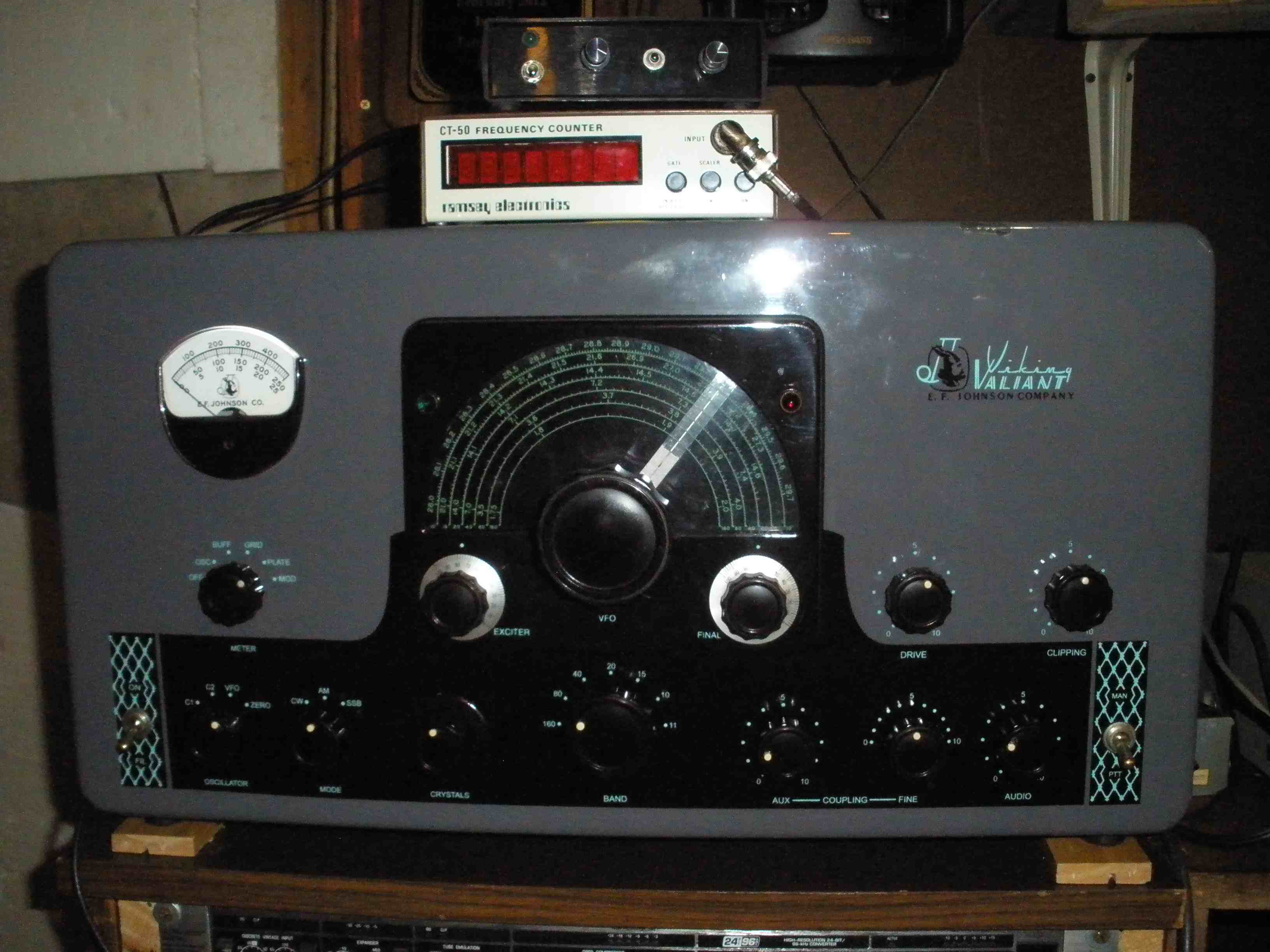
PROJECT OVERVIEW
This is not my AM rig of choice. I prefer the VIKING 2, due to its wider frequency coverage (WARC bands) and external VFO (lower drift). The
audio in stock form on both of these rigs needs a lot of work, the subject of many articles over the years. The internet has a lot of
information, some of it very good, some of it misunderstood. This will be an effort to clarify some of the design tradeoffs inherent in
the various approaches, and my own effort to take the best features of all of them and integrate them into my own unique solution.
W8JI provides some analysis of the original EFJ circuit, with extensive testing results posted.
His work shows that the original circuit just isn't all that bad, unless you want to play music or have an "announcer voice" with lows like James Earl Jones. My voice is not in that range, and Don is not a baritone either. So good low distortion communications grade high punch audio was the design goal. If you need broadcast audio sound, you will need to choose the "east coast" sound approach. Some of the new solid state all mode rigs do well, with minimal tweaks, but you need a big heavy duty amplifier. You can
go to a software defined radio, but again you need a big heavy duty amp. Alternatively, build a class E rig. This is expensive, but when you get done, you have a full legal limit AM rig with modern solid state broadcast audio sound. Expensive compared to reworking a Valiant, but a pretty good deal when compared to acquiring and refurbishing a Collins KW1, Military T368, Johnson 500 or desk KW, or a World Radio Labs 400 to 500 Watter. Or home brewing with legacy components which are difficult to find, particularly the modulation transformer. But this is comparing tangerines to pink grapefruit. The power levels of these rigs is radically disparate. I was GIVEN this basket case Valiant, and after some CPR, had to nurse it back to health. The fact is, I just plain do not have the money for any of the alternatives. This Valiant had a nice repainted and re-stenciled front panel and was just too pretty to make it an organ donor. The
guy who did the panel is now a silent key, and I wanted to preserve the original functionality and improve on it if possible. My work may give you some ideas to use on your Valiant. But be sure to do all the research on the other work that good people have done already. I include the most relevant links below.
|
VERY VERY VERY IMPORTANT! DO NOT DETACH THE FRONT PANEL WITHOUT FIRST LOOSENING THE PLASTIC VFO
DRIVE COUPLING FROM THE FRONT PANEL. IF YOU DO NOT, IT DESTROYS THE PLASTIC DRIVE. ONCE ALL THE NUTS ARE TIGHTENED IN FINAL POSITION,
(CAREFULLY ALIGN FINGER TIGHT FIRST), REDO THE VFO DRIVE LAST! |
RELEVANT LINKS FOR THE E F JOHNSON VALIANT:
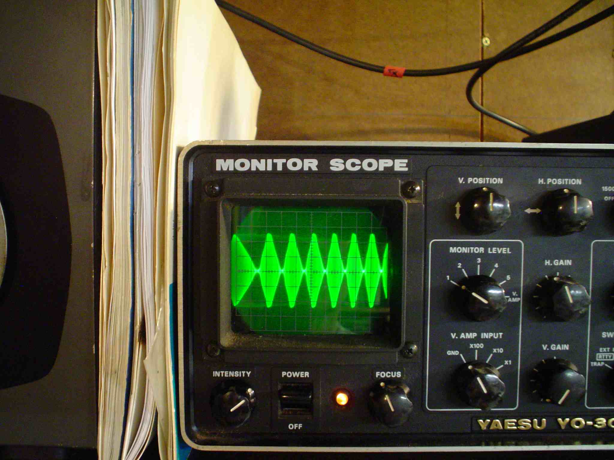
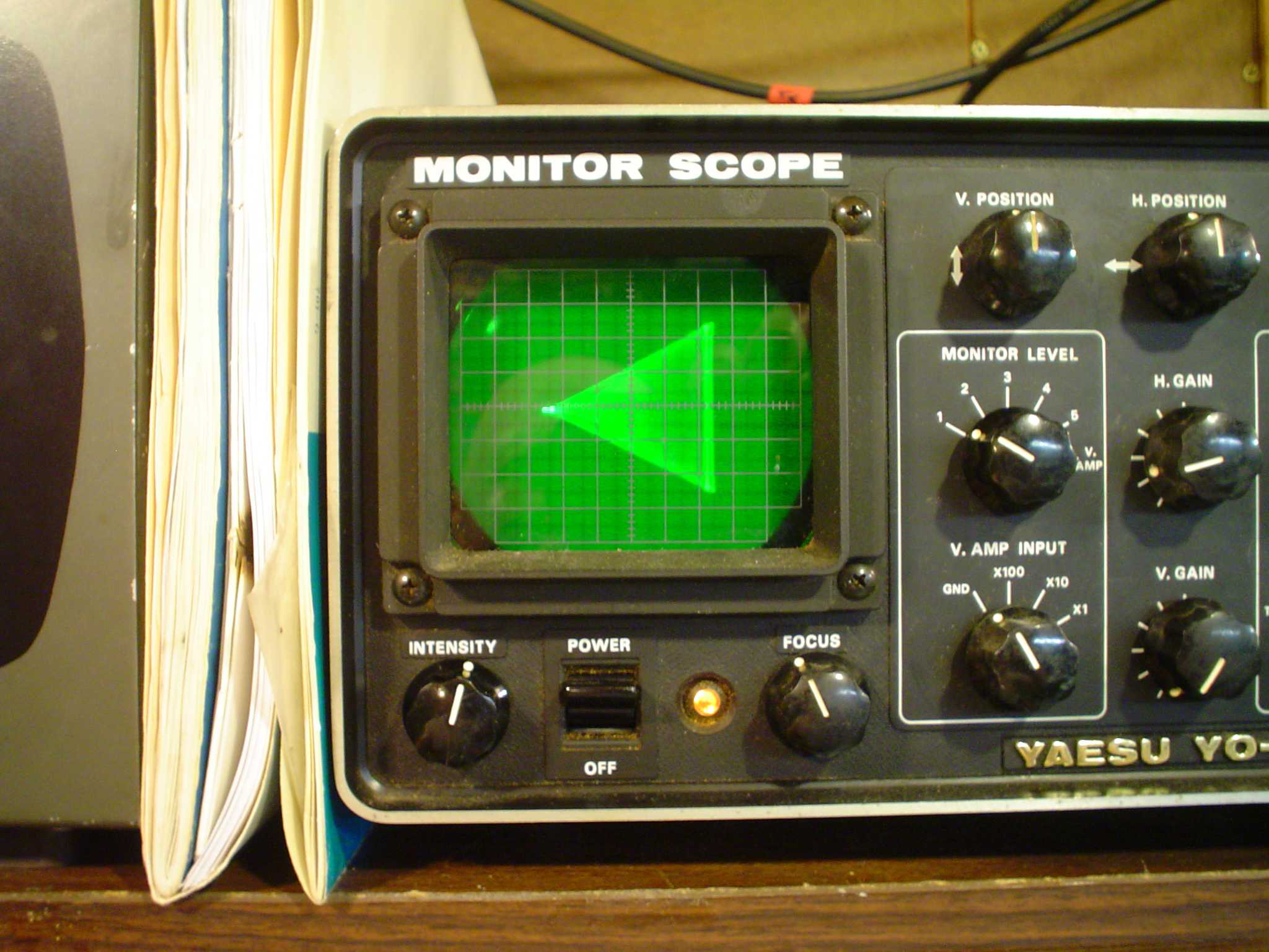
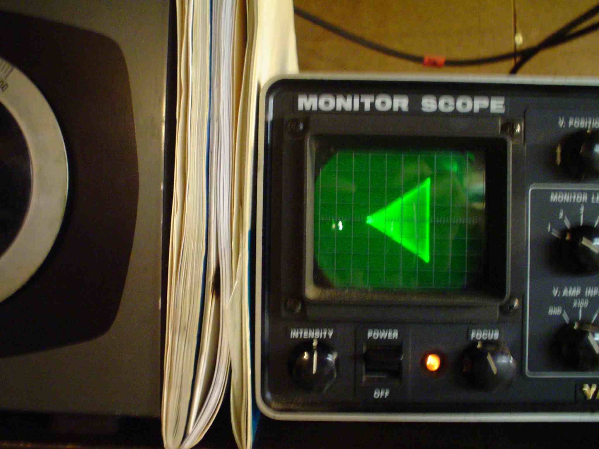
Correct scope patterns: http://amfone.net/ECSound/oscillog.htm
Stock Valiant just ain't that bad!
The Timtron has also a new posting. A must read, for the Chernobyl resistor in the VFO, the driver pot and other problems!
http://www.amwindow.org/tech/htm/valiantbytron.htm
East Coast Sound mods:
http://amfone.net/ECSound/Valntmods1.htm.
NOTE: You MUST do the high voltage B+ modulator mod to get 100% with 3 RF tubes in the final!
Part of the mods will be OK with 2 RF tubes in the final (warning, don't just unplug one tube, bias and screen resistor changes essential to prevent damage!) More discussion below.
Class E is an exciting new technology, and a great opportunity to learn new techniques. It's great to see newer hams developing this type of gear and better yet, making it available in semi kit form. I hope it grows in popularity. http://www.classeradio.com/
W8JI does not replace the nasty little driver transformer, which keeps the rig original with minimal mods. That's perfectly OK. A single ended driver has more 2nd harmonic distortion, which can cause splatter. The key element to my solution is to spend the $25 to replace the driver transformer with a modern easily available part and upgrade from the single ended to a push pull driver for the modulator AF finals. In the end, I will present a totally fresh approach with a push pull triode driver with a new transformer, which uses the original bolt holes in the chassis, and provides more than ample modulation for all three RF finals. It is necessary to employ class AB2 biasing. See the MODULATOR POWER REQUIREMENT tables at the end of the section for reference. The "east coast" approach is only capable of class AB1. The original Johnson circuit was single ended and had no feedback to reduce distortion and lower output impedance to the 6146 AF final grids, and suffered from the notorious driver transformer issues. The "east coast sound" replaced the entire driver circuit, eliminating the driver transformer, and provided inverse feedback for low distortion, but that choice limited the output stage to AB1. The addendum to the "east coast" mods, raising the High Voltage B+ for the modulator tubes gave more headroom, and probably would have provided just enough power to fully modulate the 3 RF finals. Maybe if you slightly reduce the coupling to lower RF plate current. But light loading on the RF finals results in excessive screen dissipation as noted by Timtron. Lowering the plate current raises screen current. The out of print "Care and Feeding of Power Grid Tubes" by Eimac is an essential read.
My approach, to be presented here as the project unfolds, will solve all those problems, as well as correct original design deficiencies in
the clipper and filter circuit, for clean, low distortion, splatter free audio. I may even present some of the mathematical design
methods in the audio stages, although if your eyes glaze over, you can skip that and still enjoy it.
Everyone wants to rip out the clipper in this rig and the Heathkit Apache. To remove the clipper circuit from the Apache, just turn the
clipper pot or unplug the 6AL5. The Apache is a poorly implemented partial lift of a very good circuit from the Terman Radio Engineering
handbook, which will be the subject of a later article, which also describes how to add 160 Meters to an Apache, keeping the correct circuit
Q (something which neither the Viking 2 or DX100 do properly.) Everyone ignores the small coupling capacitor in the grid of the 12BY7 driver
in the Apache, which results in tilting of the square waves coming out of the clipper (which results in splatter!) The harmonic
distortion from a single ended driver stage also can cause splatter, which is why putting a small capacitor across the secondary of the
driver transformer to grids 6CA7s is a necessity, if you keep the original design.
http://k9sth.com/uploads/Not_so_scratchy_apache.pdf
Keeping your negative peaks from hitting baseline is a good neighbor thing to do on 75 Meters at night, as well as necessary to remain
legal when operating on 7295 Mc, to prevent out of band operation of splatter products. So do not expect upper frequency response to 15 Kc
from me. Go build a class E rig or use a software defined radio with a big amplifier if that's how you roll. Both approaches yield very nice
results. I am a frugal ham because I am broke and enjoy classic tube rigs. Everyone has their own style of operating.
I acquired this E. F. Johnson Valiant as a gift from W6XR. It had "China syndromed", blowing fuses. After repair, it was
found to have excessive dissipation in the grid drive resistor, even with a vacuum tube low voltage rectifier. Some of the Timtron mods
recently posted revealed a fix to reduce the power rating of the rare 4 watt wire wound drive pot. This rig also had some of the "east
coast sound" mods, including the clever floating cathode phase inverter circuit for wide band audio. This provided excellent
frequency response, but required an external mike amp, and was incapable of driving the modulator to 100% with full input to the RF
final on my particular Valiant. It had not had the high voltage capacitor input power supply mod, which likely would have corrected
under modulation problems. I did not do the capacitor input power supply mod to increase the B+, due to the extra parts, and the
skepticism I had for the voltage ratings of the wiring, power and mod transformers, terminal strips, octal socket on the rear apron (with
jumpers) and other reasons. So I removed one of the RF final 6146s and reduced the input power to maximum 2 X 62.5 watts per tube. The
modulation then was adequate at reduced power. See the calculations and tech data from the tube manuals provided later. The raw data is
provided so that you can figure out what you want to do for yourself.
WARNING: Do not just unplug one of the finals. You MUST readjust the
screen resistor value and reduce grid drive to 2/3 of its manual stated value, along with other precautions. I will not explain this here,
since I do not recommend it as a final solution, and it takes an otherwise fine radio and uses it to far less than its full potential.
However, it is a viable way to make the east coast sound mods work without making the power supply mods that boost the HV B+ to 1000V on the modulator to get the requisite power to 100% modulate
the rig with hi-fi audio. I deliberately do not include all the 2 jug mods because I do not want to get into supporting it, or arguing the
case for doing the mods that way. The circuit constants employed in the Viking 2, which IS a 2 jug rig, are a good starting point. I did not
do extensive testing to verify them, and you are on your own if you want to pursue that as a permanent solution to the under modulation
problem. Apparently, many people have had success doing the mods in the way described exactly on the web page links provided here. I have
heard NO negative comments from anyone that has done those mods. I just choose to do it differently, and am providing the information
for my work here. In reality, the RF power output differences between a 2 jug rig with fat audio and a 3 jug rig are trivial and will not
result in any noticeable changes in the other guy's S meter reading. My contention is that better average audio modulation through
limiting, clipping, or compression WILL make a very noticeable difference. Further, the outboard Behringer 2496 (which was also a
freebie) was nice, but not something that I would have done by choice. It actually sounded OK after a lot of experimentation with
settings, but the Valiant was no longer a complete self contained unit. Most of the guys running the east coast mods seem to be running
a lot of extra equipment, compressors, equalizers, and so on, which increases the cost and complexity of the overall system. I will keep
it and play with it more. Additionally, I noticed significant increases in modulator plate current when running heavy amounts of
low frequency from the signal generator. This is due to the inductance limitations in the modulator transformer. The feedback
kept the response relatively flat, but it was making the mod transformer work very hard by driving it harder. And the 6146
modulators just did not have the skrote to make the power needed at mid frequencies, let alone at the bottom end.
In the end, I wanted to make the original "one box" Valiant live up to all the manufacturers claims as far
as possible, while not risking unobtainium replacement components.
The clipper had been removed in the "east coast" mods, so no modulation limiting was in place. This
resulted in weak audio, if you kept the gain down to avoid distortion or hitting the baseline (0% modulation). I found a way to correct this
problem by changing the CLIPPING POT value, as well as redesigning the mike amp for less distortion, solid stating the clipper, and changing
the input and output drive impedances to the clipper and filter (which I also reinstalled) to prevent splatter which would result either from
over modulation or clipper distortion products. This was good enough to get it on the air for a shakedown cruise for the AM QSO party, to see
if would hold together good enough to justify further work.
The real work yet to come is getting a quality driver transformer and a push pull triode driver stage
with inverse feedback properly installed.
Links will be provided, so you can compare them to my approach. Only you can determine what is appropriate for your own style of operating.
This project is definitely NOT recommended for people who are not familiar with soldering and electronic techniques or the extra safety
precautions required for working on high voltage vacuum tube technology.
I do not want to provide partial information, that may be incomplete or misunderstood.
MODULATOR POWER OUTPUT CONSIDERATIONS (Math to make your head hurt.....)
The essential technical data you need on the modulator power is listed below, because the manuals
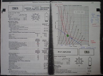
I have access to are hard to come by these days. I may post some of the tube specs on this website. I have the complete set of binder
style GE manuals, with characteristic curves.
The RCA Transmitting Tube Manual TT-5 rates the STANDARD 6146 in push pull for AB1 and AB2 service as shown below:
- AB1 600V: 95W *see comment below
- AB1 750v : 120W
- AB2 600V: 113W
- AB2 750V: 131W
The Sylvania Tube Manual 1979 rates the 6146B in push pull:
- AB1 600V: 96W – Not enough difference to justify switching to 6146B
- AB1 750V: 124W
- AB2 600V: 130W – very significant improvement at 600V, if the driver stage is fixed
- AB2 750V:148W
I do not question that you can get more sauce out of the 6146 at 1000V or more. It does exceed
ICAS ratings. More importantly, it seems scary to me looking at the wiring, terminal strips, disc ceramics, and the 9 pin plug and jumper
plug. Plus modulation transformers are getting hard to come by. Someone is apparently stepping into the void left by Peter Dahl.
The necessary power to 100% modulate the 6146 RF finals is as follows:
- In the RF final, standard 6146s are good for 112.5 mA at 600V or 67.5W MAX input per tube in ICAS AM telephony service.
- Specified RF Output 52W MAX per tube approximately.
- The EFJ Valiant manual calls for 310 to 330 mA plate current for AM service, which is about right for 3 tubes at 630VDC nominal.
(Interesting side note: many manufacturers like Eico and Heath did not reduce the RF input power from 90W to 63W per 6146 in their
manuals! Do the math and reduce power for better tube life. EFJ got it right and runs the 6146s at 450 mA on CW.)
This matches E F Johnson published spec of 200W AM input and 275W CW input for 3 RF tubes in
the stock final. At 80% efficiency, this works out to 160 W output on AM and 220 W output on CW for a bone stock Valiant. Not measurably
louder than a Viking 2, but still a cosmetically nicer one piece package with the VFO internal. I will get to the Viking 2s in storage
later, if I can get this one on the air in some form now.
- Running 3 6146s in the final at 310 mA X 630V = 195W INPUT or 65W per tube.
- The 330 mA in the Johnson manual is OK if you realize that cathode current includes screen current of about 10 mA per tube.
- This requires a modulator OUTPUT of 98 W.
- *At 600V, observe that only 95 W is available under optimum conditions in class AB1 for standard 6146s.
On paper it looks almost OK. In practice, if the tubes are not brand new quality, it doesn't make
it on the scope monitor. The audio peaks just fold over, regardless of adjustment of the inverse feedback pot.
Partial solution is reduce RF plate power input, with cautionary notes included on screen dissipation.
Observe that 130W is available for 6146Bs running class AB2 – PROBLEM SOLVED! And only running
standard 600V! So, this is the right final solution. In the interim, using 2 RF finals will cob it till the project is finished in its entirety.
- Running 2 6146s in the final at 200 mA X 630V = 126 W INPUT or 63W per tube.
- Likely MAX output = 100W at 80% efficiency, about right for good harmonic content.
- Plate efficiency for a class B amplifer can run 60% to 70% depending on transformer losses.
- Class C plate efficiency depends on tank Q but may approach 85%.
- These figures come from "The Radio Handbook" 15th edition by W6SAI known as the "west coast" handbook.
- This temporary fix requires a modulator OUTPUT of only 63 W, definitely OK.
- Running this as a "2 jug" rig does not use the rig to its full potential, but it gets it on the air to see if further repair work is warranted.
A side note: All 6146s are not created equal:
http://k9sth.com/uploads/The_6146_Family_of_Tubes_1.pdf
HOW
THIS MODIFICATION IS DIFFERENT FROM OTHERS
This article is not meant to be a highly organized dissertation. It is a bunch of random musings about the design process which may be of help to you in deciding what to do.
I make reference to other people's work in this article. I researched
what others were doing as I was developing my plan of action, just as
you are looking my ideas over. Nothing here is meant to denigrate
their designs. I looked at their choices, and made different choices
for myself. I offer the reasoning for why I departed from those prior
articles. It is not throwing rocks at someone else's work. Everyone
has their own solution; just because they differ does not mean that
one or more of the approaches is wrong. I present my reasoning here,
and the alternatives to my approach; you are free to explore options.
I hope you will find something useful.
As a reference comparison, the stock Collins 32V series specifies 8%
distortion at 90% modulation, with a frequency response of 200 to
3000 cycles at 2 dB down. The Valiant can do better than this, with
any of the published modifications. Certainly the 32V can be improved
with the mods available from various sources also, but I offer this
as a comparative level of performance.
The
parentage of my final version Valiant is as follows: nothing of the
"East Coast" mods survives. The RF stage, modulator
output stage, and VR tube modifications closely parallel the work of
WA1HLR as posted on line. We all owe Tim a lot both for the
information he shares freely with others as well as the preservation
of the art and science of classic AM radio. The fixes for flaws like
the drive pot also come from him. From the grids of the 6146
modulators to the line or mike input, I wanted a better driver
transformer, so all the rest of the design work is mine.
The
Valiant is prone to failure of terminal strips and wiring due to high
voltage arcs. This problem is why I did not do the extra mods in the
"East Coast" version to increase the modulator B+ to
1000V. Perhaps if I had done those mods and they worked without
flashing over, I would never have gone this route. As is stated in
Tim's article, you have to do the whole set of modifications in any
article to get the performance increase expected; half way just does
not cut it. I failed to do that in the case of the "East Coast"
mods and did not get 100% modulation without distortion. Maybe you
can get a HiPot tester on loan from a friendly electrician to
determine if your rig will tolerate the higher B+. Of the five
Valiants that have crossed my workbench, none of them appeared up to
the task. Another tack is to reduce the RF plate power input
(approximately 300 mA according to W8JI or only 10% of 200 Watts).
Note that this absolutely requires Tim's change to the RF screen
resistor to increase it to 20K or possibly 25K. As plate current is
lowered by tuning controls, the screen current INCREASES, exceeding
dissipation of the screen. Raising the screen resistor corrects for
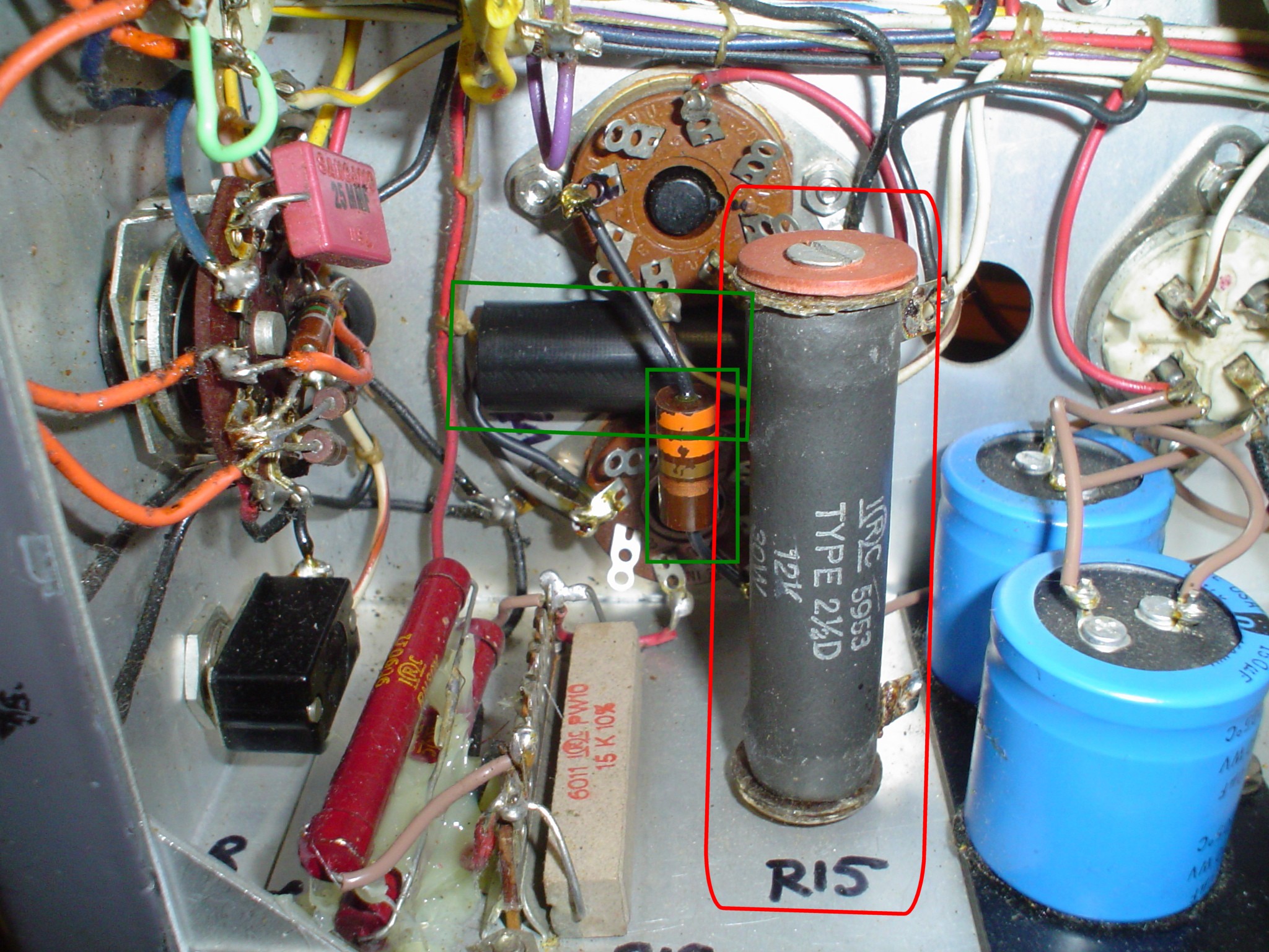
this. The "East Coast" mods refer to changing to a VR150
and references R16 for 20K; this is the wrong resistor for the VR
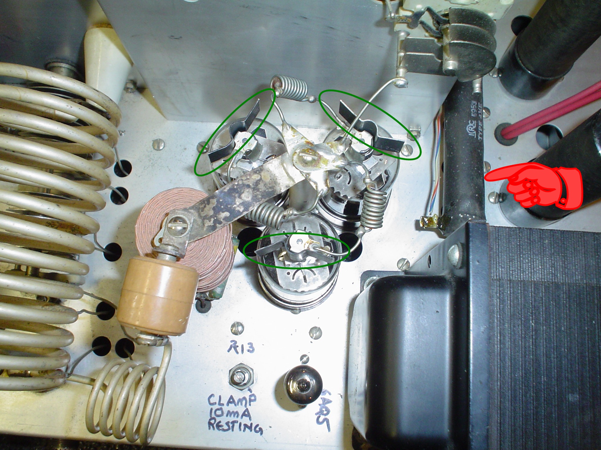
tubes. The 25 Watt 12K resistor is the VR tube resistor located under
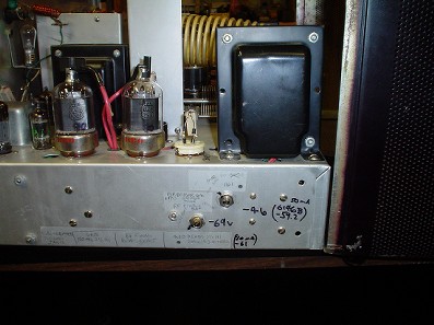
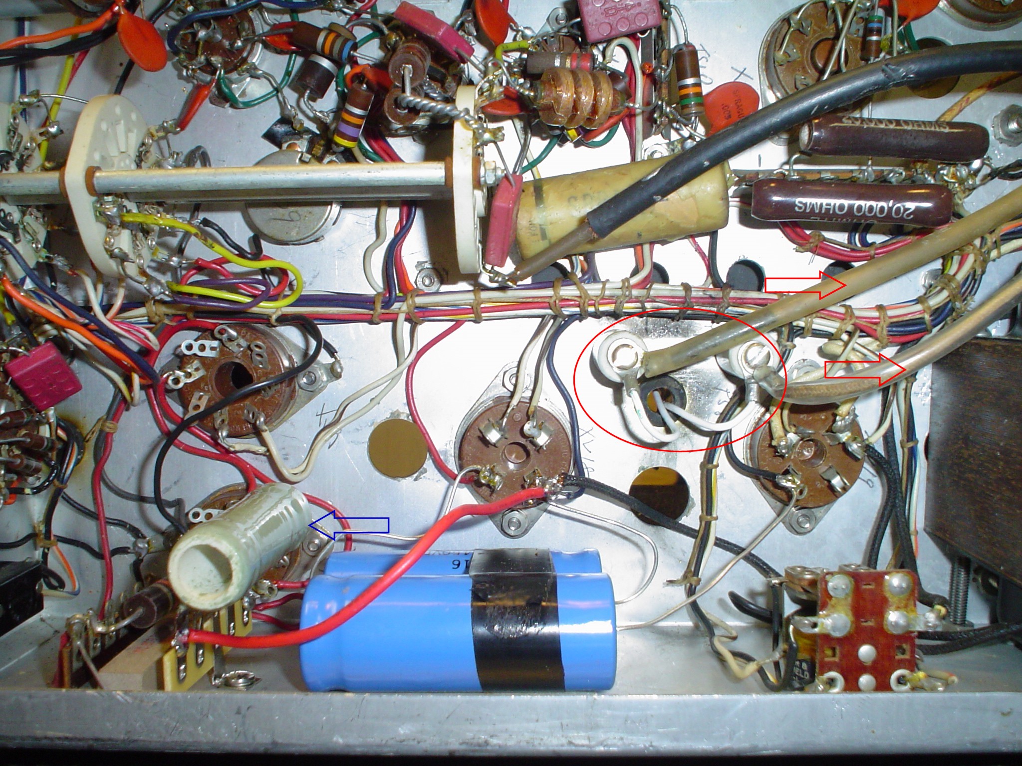
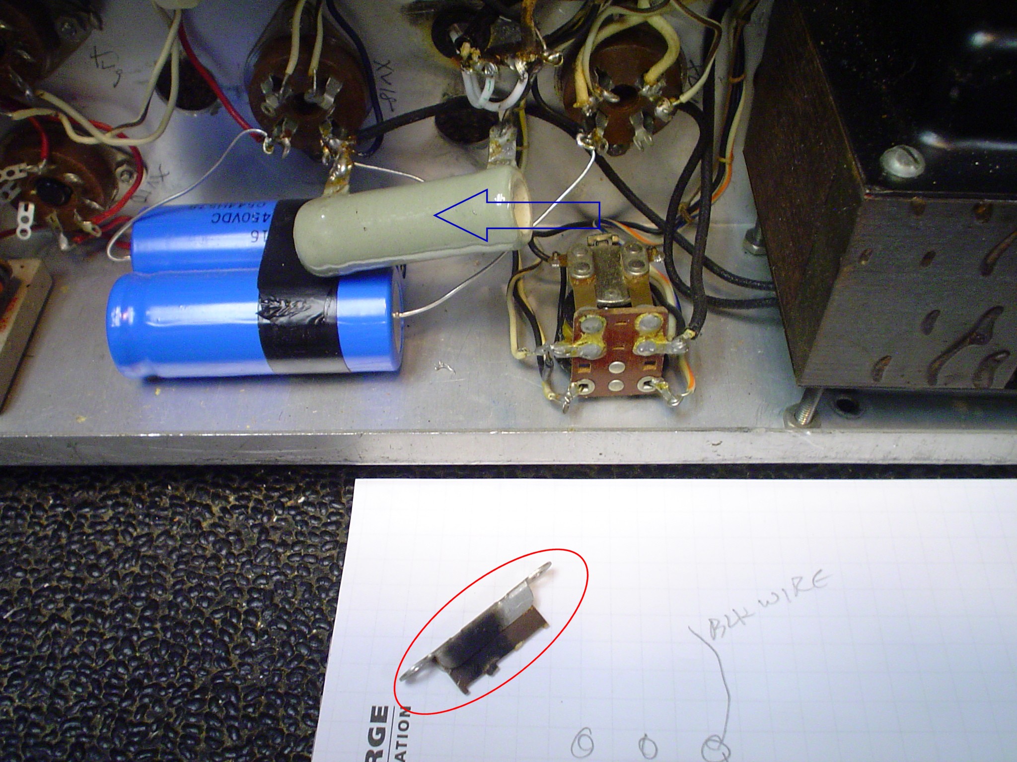
the chassis near the 866 sockets. I show in pictures the change in
mounting for the 25 Watt resistor. One of them is mounted with a
screw through the center and the other is on a new terminal strip. It
would have been better from a heat standpoint to put it ABOVE the
chassis, but finding a spot for it where it did not increase the
heating of another component would have been difficult.
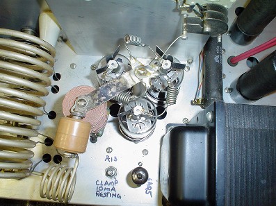
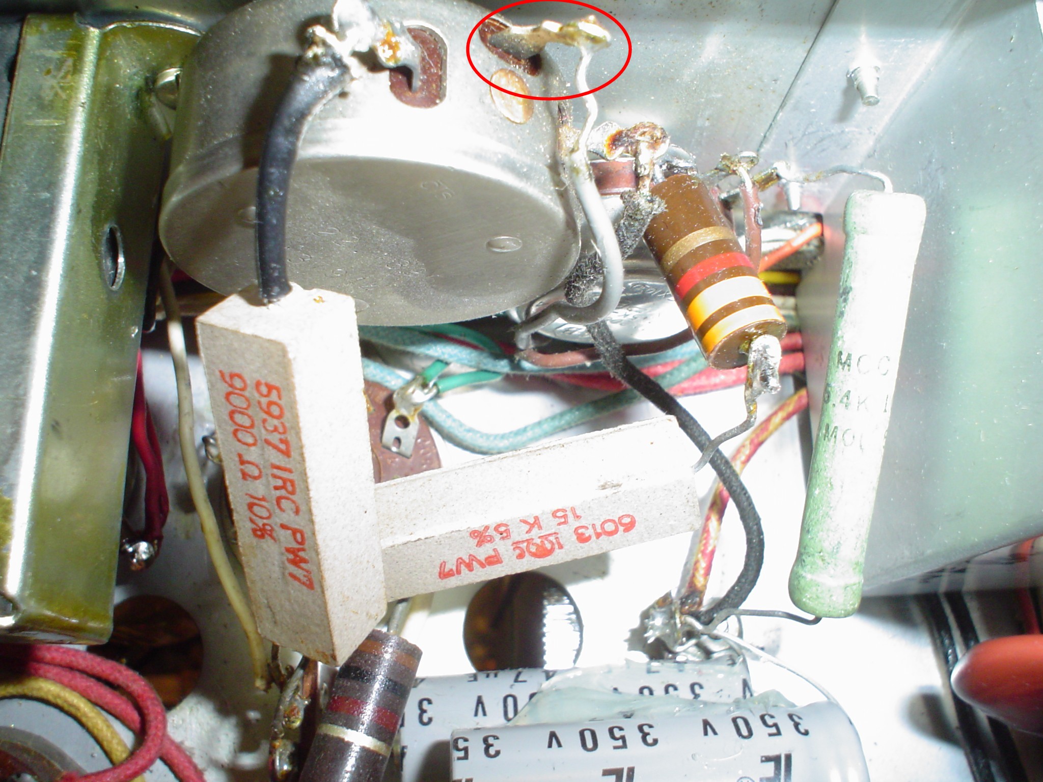
The
12K 50 Watt resistor is above the chassis and is the RF power
amplifier screen dropping resistor. It needs to be 50 Watts because
in CW key-up conditions, the bottom end is grounded by the 6AQ5 clamp
tube. The 25 Watt resistor should be moved above the chassis and
increased if you are lowering the AUDIO power amplifier screen
voltage. INCREASING THE VALUE OF BOTH is a possibly a good idea, to
increase RF stage modulation linearity and correct the modulation
transformer impedance mismatch by changing the plate resistance of
the modulator tubes. Do not forget to insert a 10K resistor in the
control grid bias supply for the RF stage to increase the amount of
grid leak bias and set the RF stage resting plate current in SSB mode
to 100 mA as described in the Valiant 2 manual for correct RF PA grid
bias. You just might get enough to make you happy with this mod
sequence without going to the 1100Volt B+. I did not try this, as I
did not think of it at the time. A 10% drop in RF power definitely
will not be noticed and will retain all the nice features of the
"East Coast" mods. In retrospect, I wish I had tried to
make it work, just as an exercise in comparison. However, I chose to
get class AB2 to get the original power ratings from the Valiant, so
that is the modification discussed here.
Take a look at
my separate article with pictures of the previous damage inside an
unmodified Valiant, and you will understand why I did not proceed
with mods posted on the net. People have done the "East Coast"
mods successfully with the high B+ mod implemented and experienced no
problems, so decide for yourself what you want to do with your radio.
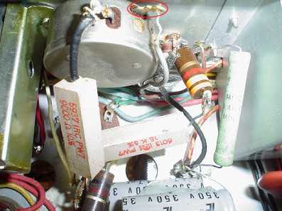
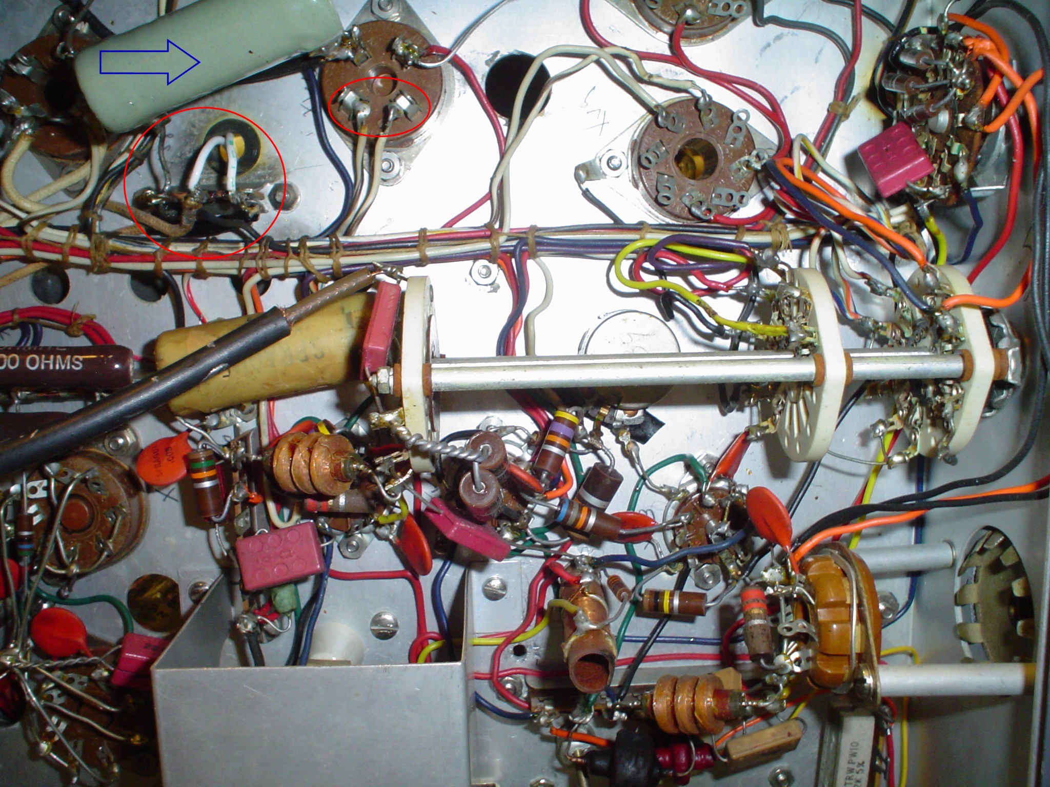
Inspect carefully for any arc points in the radio before doing any
mods. I include pics of arcing on the terminal strip for the
filaments of the 866. Also, the wiring for the HV plate filter choke
are insulated with additional sleeving. There is another terminal
strip near the LV fuse for the 866 filaments which can cause trouble.
Sleeving may be required on the 2.5 VAC filament wires into the LV
transformer. The 4 pin sockets may arc. (The Viking 2 is notorious
for this, and all that is required is to put insulating spacers and ¼
inch longer mounting screws on the sockets for the 5R4s.) Replace the
866s with 3B28 tubes to avoid mercury warmup issues with resulting
flash over upon application of HV power. I have commercial solid
state replacements in my rig. The modulator transformer terminal
strip is a possible problem. Ceramic standoffs help. The back panel
jumper connector J8 is a possible problem. All these potential
problems are the reason I did not attempt the "East Coast"
mods that raise the HV B+ to 1000 V on the modulator.
Some people have had success with this approach, but looking at the wiring
harness and all these known failure points, I sought another
solution. This one worked out OK for me. Look it over, and see if it
will work for you. A new $25 driver transformer goes a long way
toward improved performance. This one makes full modulation and
decent frequency response without exceeding ICAS tube ratings or
risking failure of old wiring due to "hot rodding" the HV
power supply. Further, I have used this transformer in a number of
vintage restorations successfully and have a high level of confidence
in its potential.
Both WA1HLR and
W8JI have found that the RF stage is biased on the grid improperly in
the EFJ design. Tim recommends 5K or more to add grid leak bias. W8JI
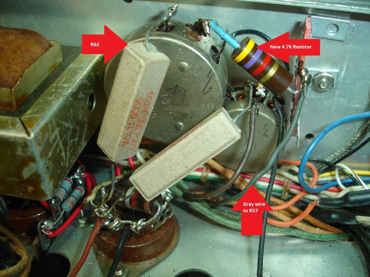
recommends 10K. I used 4.7K 2 W to increase the grid leak bias to
obtain the 6146 specified voltage of -85 volts. The "East Coast
Sound" mods do not address the RF biasing problems at all. They
reference increasing a 12K power resistor to compensate for the VR150
change to the modulator, but it is the WRONG ONE for the voltage
regulators. If you do not change the correct 12K resistor, excessive
current is sent to the VR tubes. The full standard 6146 specs are
included in my article, so you can follow my design process. Not even
all commercial sources of 6146 specs agree, so I show the range and
offer my opinion.
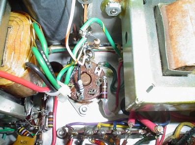
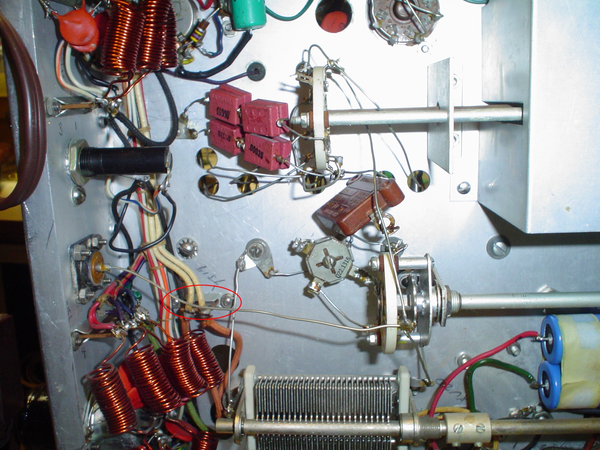
 WA1HLR mods grid bias resistor; disconnect this wire and insert 4.7K WA1HLR mods grid bias resistor; disconnect this wire and insert 4.7K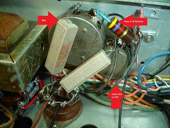 Thanks to David Phillips for showing his Valiant Grid Bias Resistor Installation. Thanks to David Phillips for showing his Valiant Grid Bias Resistor Installation.
W8JI
does not comment on the screen resistor. Neither do the "East
Coast" mods. WA1HLR recommends 18k to 20K. I performed tests
and found Tim was right on target. My rig uses 7.33K in series with
the original 12K for a total of 19.3K, using resistors from my junk
box. The screen current is now closer to the 7.8mA 6146 spec. I get
8.2mA per tube and about +170V. The original voltage was higher than
200V. The 6146 spec is +150V. In the end, maybe 20K or even 22K would
have been better. I will experiment with this later and update this
page. Maybe W8JI's higher 10K grid resistor would be better, more
like 100V of grid leak bias, but the resting current might have to be
more than the plate dissipation of the tubes, like almost 125 mA in
SSB mode; would the 6AQ5 clamper have enough snot to pull the plate
current down in key up conditions? I don't know, I did not try it. I
have confidence in Tim's work, tried it, and the scope does not lie.
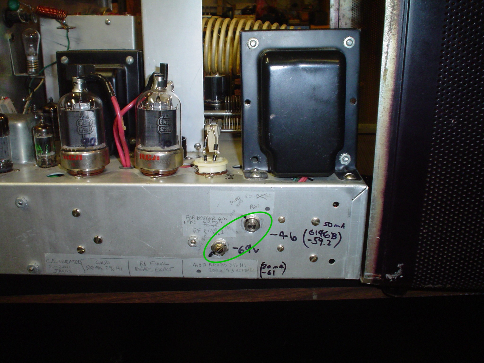
It is critical to note that the Valiant One with the old slider
resistor adjuster calls for 50 mA resting current on the RF finals in
SSB mode. The Valiant 2 with two 4 Watt rotary screwdriver adjuster
resistors calls for 100 mA. Tim recommends 100 mA per a conversation
we had on the air. Use 100 mA as it is a lower fixed bias voltage,
allowing the grid leak resistor to do its job properly. If you have
not updated your Valiant One to the Valiant Two bias supply adjuster
configuration, consider doing it now before the modifications begin.
WA1HLR and the
"East Coast" mods reduce the value of capacitors across
the secondary of the modulation transformer. The audio system WILL
reproduce 50 cycles to 8KC or more from the line input using several
designs, depending on the capacitor value. This capacitor is
"building out" the modulation transformer. It has a
similar effect to a discrete pi network LC network between the
modulation transformer and the RF stage. But it does not come with
the risks associated with the high level splatter filter. I may post
some information on both techniques, since most of that information
is out of print. Some people maintain that you want to make the
output stage wide open and do all the frequency contouring at the low
levels. The problem arises that the power output stage produces
harmonic distortion which has the same effect as splatter, or can be
inadvertently overdriven, as W8JI and I point out. Limiting the
harmonic distortion content with a high level splatter filter or
building out the mod transformer protects from this. Think about it;
do you really want to be 20KC wide on 7295 or 75 Meters at night? I
opened it up a little bit from stock, but much less than Tim
recommends. With reduced harmonic distortion of my push pull driver
and improved driver transformer compared to the stock or modified
single ended driver, it is OK to do this. You CAN provide a choice of
high frequency performance by putting the modulator "build out"
capacitors in a J8 plug that can be changed to fit the operating
conditions.
WA1HLR
points out that the 6146B modulator screens need a series resistor of
about 270 ohms and changes to the regulator tubes to reduce audio
energy present at the screen. The "East Coast" mods use
1K in series with the screens; perhaps a higher value might help. He
recommends a 10 to 20 uF capacitor to stabilize the screen voltage
and a 330 ohm resistor to prevent the VR tubes from motorboating in
and out of ignition (called relaxation oscillation). I adopted this
fix and found it reduced distortion at drive levels in excess of 70%
modulation just as he said. See the schematics for the wiring
details. See the photos for the mechanical details. This is a key
modification that is absolutely essential to the proper operation of
the whole system described in either his or my article.
The "East
Coast" mods use 1K resistors in each screen and 13 ohms in each
cathode separately. The HV is 1000 V from a modified supply though,
and operates AB1. Class AB2 runs heavier screen current and may not
need as big a resistor to get the necessary effect. Use of cathode
bias (the 13 ohm resistor) is not a good idea for class AB2; a stiff
fixed bias source is the only way to go. This all may account for the
differences. I did not try these values, since the ones Tim
recommended worked for me.
It might be
interesting to try an "ultralinear" output stage as was
popular in hi-fi equipment. This might play well in the Apache, as
6CA7s frequently are used in this fashion. I do not know if 6146s
lend themselves to the ultralinear mode of operation. Since the
Apache uses the 6CA7 far beyond its voltage ratings, the 6146 would
be a good choice to replace the 6CA7, and the plate impedance of the
6146 might allow it to just bolt up to the existing mod transformer
in the Apache. To do it in the common configuration, you would need
screen taps (about 20% up from the B+ terminal) on each side.
However, you might be able to use resistors across each side of the
primary winding for each screen supply. This would waste some audio
power in the resistors. It would also exceed the screen voltage
rating for the 6146, unless you reduce plate supply voltage. This
would also reduce output power. There is nothing in this thread of
thought that appears useful in the Valiant without dramatic redesign
of the whole radio; it would be better to start over with a fresh
design. Distortion in the configuration I would up with is good
enough for my use. Some of the ideas in this article could work out
for you on your Apache, but this is NOT an article about the Apache.
That is another story which I may get to, along with putting the
Apache on 160 meters.
WA1HLR
uses the defunct Valiant SSB function position to operate a low power
transformerless "goose tube" screen modulator similar to
the DX60 for reduced power operation. You may find the option
desirable. I was impatient to get this one on the air so I did not
pursue that. If you wanted to use the Valiant as a driver for a legal
limit amplifier, there are better options. On the other hand, if you
wanted to use the Valiant that way to drive a "death star"
class linear, it could be a good thing. It does leave the 6146
modulator tubes lit, unless you provide a relay to power them down in
screen modulator mode.
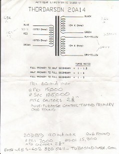
I wanted to
maintain the clipper function. You may debate the wisdom of this, as
I discuss later. It is essential to retain the excellent low
frequency response provided by this 20A14 transformer to prevent
canting of the low frequency square waves coming out of the clipper
if you wish to enjoy the full benefit of its operation. When using
low level speech clipping, it is essential to reduce excess low
frequency response in the stages preceding the clipper and get the
stages following the clipper as close to DC coupled as possible. This
criterion is generally NOT observed in transmitters of this era such
as the Apache. The Apache uses small coupling capacitors and a driver
transformer which are inadequate to use the clipper properly, causing
its "scratchy Apache" sound. The Apache clipper, which is
an exact copy of a circuit in Terman Radio Engineer's Handbook, is
not the cause of the problems at all. Heathkit's defective
implementation is the true culprit. When using the line input with
outboard audio chains, you will appreciate the 20A14, which CAN drive
the 6146Bs into full class AB2 and still have good frequency response
without running 1000V on the plates of the 6146 modulators.
Many people
remove the clipper from their rig. They lose the over modulation
protection afforded by the limiter. It is better to make the limiter
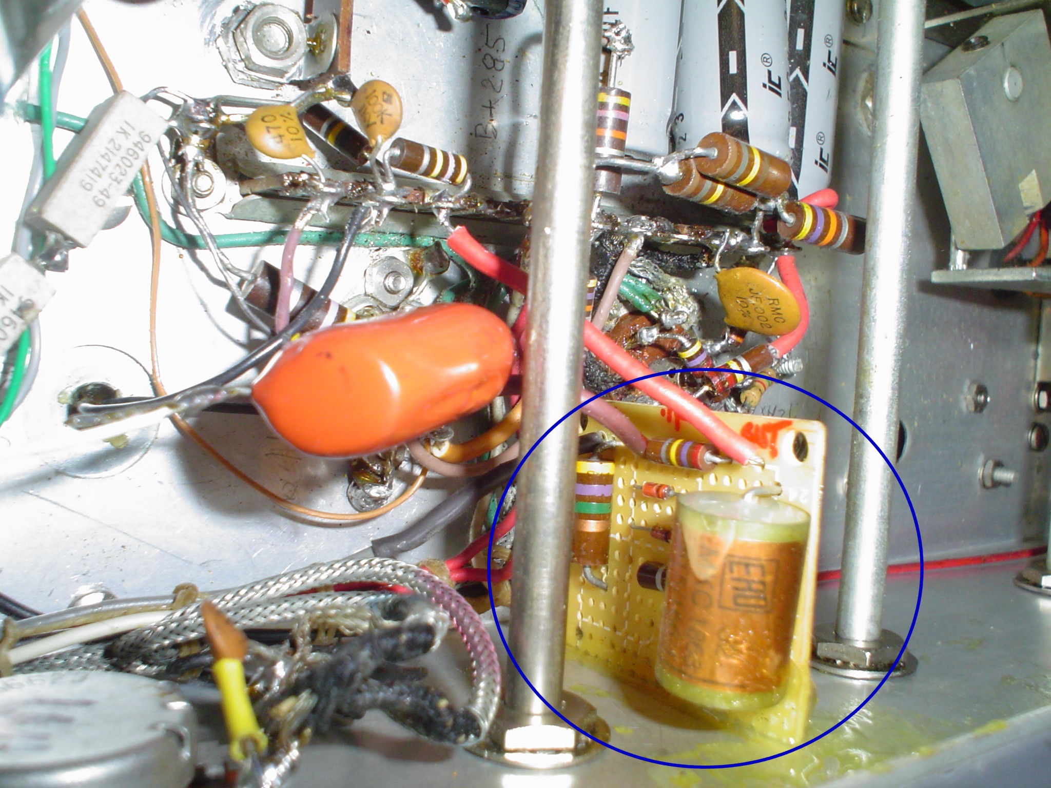
work right. My design does that. The limiter (clipper) is solid state
diodes on a small circuit board. This frees the socket used for the
6AL5 for a 6AV6 amplifier tube for impedance matching and gain and
circuit design flexibility. I found that increasing the resistance of
the pot and another resistor noticeably improved the waveform in the
limiter. While the Johnson values are the same as common handbook
circuits, I found my mine seemed to work better. Driving it hard
makes clean looking square waves. The original circuit looks terrible
and depends on later filtering to reduce that. W8JI leaves the
clipper in and recommends shorting one of the diodes with a capacitor
if you want to only limit the negative peaks and allow upward
modulation to 130%. How he achieves this upward modulation percentage
without work on the output stage to make it work in AB2 or gets low
distortion output escapes me. I felt that 3 to 6 dB of gain
compression would provide better average modulation level punch than
the asymmetrical modulation, which vintage receivers do not tolerate
well. Synchronous detection will love the upward peaks. Everyone has
their own solution; just because they differ does not mean that one
or more of the approaches is wrong. I present my reasoning here, and
the alternatives to my approach; you are free to explore options. In
practice, no one seems to complain about smaller levels of clipping.
It just prevents splatter. Once you exceed 10 dB, people do not like
the sound for casual local ragchewing, but it does help some in bad
conditions. 18 to 24 dB will likely get you a "military sound"
audio report, and the EFJ manual tells you that. Excessive use of
clipping or any nonlinear compression techniques causes
"intermodulation distortion", a gravelly sound. This
results from harmonics and mixing products between all the
fundamentals and harmonics contained in the original voice signal. I
am sure that you have heard over processed SSB stations, especially
trying for a contest mode signal. Even properly done, it gets the job
done, but not nice for rag chews. Exercise common sense and
moderation in all things. If you do not want to use the clipping
function, turn down the gain control, don't hack it out. Or use the
points indicated in my schematics to bypass the function you do not
want.

For
more authoritative information on frequency range for voice
communication and optimum clipping levels, consult the Radiotron
Designer's Handbook. It is out of print, but you can find a copy for
about $30. It is definitely a good resource.
If you want
more high frequency response, adjust the values of the modulator
secondary shunt capacitors as well as the small cap across the phase
inverter. My values were checked out by a local friend with a flex
radio and show an upper limit of 3.5 KHz "on the air".
Vintage receivers like the HQ170 and 180 as well as the SX100 and 101
are not likely to hear much higher than that. You can tap into an
HQ170 or 180 at the 2nd IF of 455 KHz and get a hi-fi
signal under good conditions, but that is another story. Under
optimum conditions, with no band crowding, you can get away with
running a wider signal. One option is to put an "old school"
high level pi network LC splatter filter in a box mounted to the back
of the Valiant cabinet plugged into J8. A second standard plug with
only jumpers would be on hand to allow wider bandwidth. Use adequate
insulation and safety precautions. These are deadly voltages and may
contribute to arcing problems as I discuss in this article. I may
write this option up later, or get back to me if you have success
with it. You could also mount the capacitors used to "build
out" the mod transformer in the J8 mating plug, possibly with
multiple plugs available for quickly adjusting the high frequency
response of the system.
WA1HLR
recommends a feedback loop all the way around the whole system,
including the modulation transformer and the driver transformer
inside the loop. This is very tricky to include the phase shifts of
both transformers. The stock driver transformer shows a nasty peak in
response above 150KHz. This indicates large amounts of phase shift at
high frequencies two decades below that, within the audio spectrum.
Within a feed back loop containing two transformers, oscillation in
the 30 to 150 KHz region may occur, even when the phasing of the
transformers are supposedly "correct" in the audio range.
Read up on Nyquist diagrams if you want to see more about these
problems. When I was experimenting with this setup, I had bad ringing
and instability on square waves used for tests. Even with the better
transformer, I decided not to attempt including both transformers in
the feedback loop on the first design iteration. I may try this
later, and update the main article. Tim uses a swamping resistor
across the stock transformer to deal with this problem. I tried 18K
to 33K with 0.005 in parallel. But I only was able to tame the stock
transformer with 10K in parallel with 0.005 uF across the secondary.
That was too low a resistance, which is why Tim uses 47K and no
capacitor. He seems to get the system to work for him with both
transformers in the loop. In the end, WA1HLR's recommendations for
the 6146B modulators screen circuit and regulators reduced the
distortion on peaks above 70% modulation to a tolerable level that
made the inverse feedback with the modulation transformer in the loop
unnecessary to obtain acceptable performance. I elected the simpler
way at this time. It also allows circuit testing of the low level
stages with the HV supply turned OFF. With feedback including the two
transformers solution, gain and voltage levels and frequency response
will change from the transmit mode to the standby mode since the
6146Bs are inside the feedback loop. In addition, with the mod
transformer in the feedback loop, the modulator tubes will pump
frightening amounts of current into the mod transformer trying to
maintain the low frequency response. If you are sensible about the
amount of low frequency energy you apply, and do not try to test the
full power output at lowest frequencies, you might get away with it
OK.
All the low
level stages in the audio chain have unbypassed cathode resistors in
my design. This results in low distortion from each stage owing to
the inverse feedback from this configuration. Distortion in each
12AX7 stage can exceed 2% without inverse feedback. Most designs I
have seen employ cathode bypass capacitors, which do not take
advantage of this improvement in the low level stages. WA1HLR uses
bypass capacitors, then offers the suggestion of using a lower gain
12AU7, which has the same effect of my modification (which has lower
gain without the bypass cap). But that design does not have the
benefit of the lower distortion and noise resulting from the inverse
feedback of my design.
A magic
incantation I learned from an ancient wizard: "Inverse
feedback, reduces gain, noise, distortion and output impedance and
raises input impedance." Use the 12AX7 as I show with no
cathode bypass capacitors. It has more than enough gain with a good
microphone and is cleaner.
Many recommend
a 10 Meg resistor in the mike circuit. I found that hum was excessive
in my rig with a D104, so I stuck with a 3.3 Meg and smaller coupling
capacitors, especially in the input stage. Encasing the resistor in
shielding is said to help. Use shrink sleeve to cover the resistor
and cover it with grounded braid. I do not have a deep voice, so I
did not need to have extreme low end performance in my solution.
Experiment with the two 0.002 uF coupling capacitors in the 12AX7
stage to add lows. The mike wire passes by the filter choke and
transformer, and is in a harness bundled with AC wiring. Possibly
using DC filaments in the audio section would help, but I did not try
it. Tim suggests making the 12AX7 filament wiring as a shielded
twisted pair "home run" style back to the filament
transformer. I considered removing the MAN – PTT switch and
placing the mike connector there at one point. This rig had a custom
paint job. It made no sense to compromise its appearance. I have made
no changes above chassis that detract from its appearance.
Boomy
lows of overdone "broadcast audio" was not a goal of this
project, as I stated earlier. If you want that, you probably have an
audio processing rack and would be better off feeding that to the
line input connector. The line input accepts about 0.5 to 1 Volt with
excellent frequency response. I had to move it before the low level
LC splatter filter to prevent it from being too wide when using a
Behringer VX2496 with some presence rise. If you want a "wide
body" signal, move the connection after the LC splatter filter,
but get a good air check from a friend. You will know what capacitors
to adjust in the later modulator stages if you own this type of
equipment to get the signature sound you want. The driver transformer
will carry a lot of lows, but remember that the output modulator iron
is not designed for this and a lot of current flows in the winding
trying to produce those frequencies. When I had feedback that
contained the output modulator transformer in the "East Coast"
configuration, I noticed frightening amounts of plate current trying
to maintain a flat frequency response for the lows when doing
frequency response checks, even at only 30% modulation.
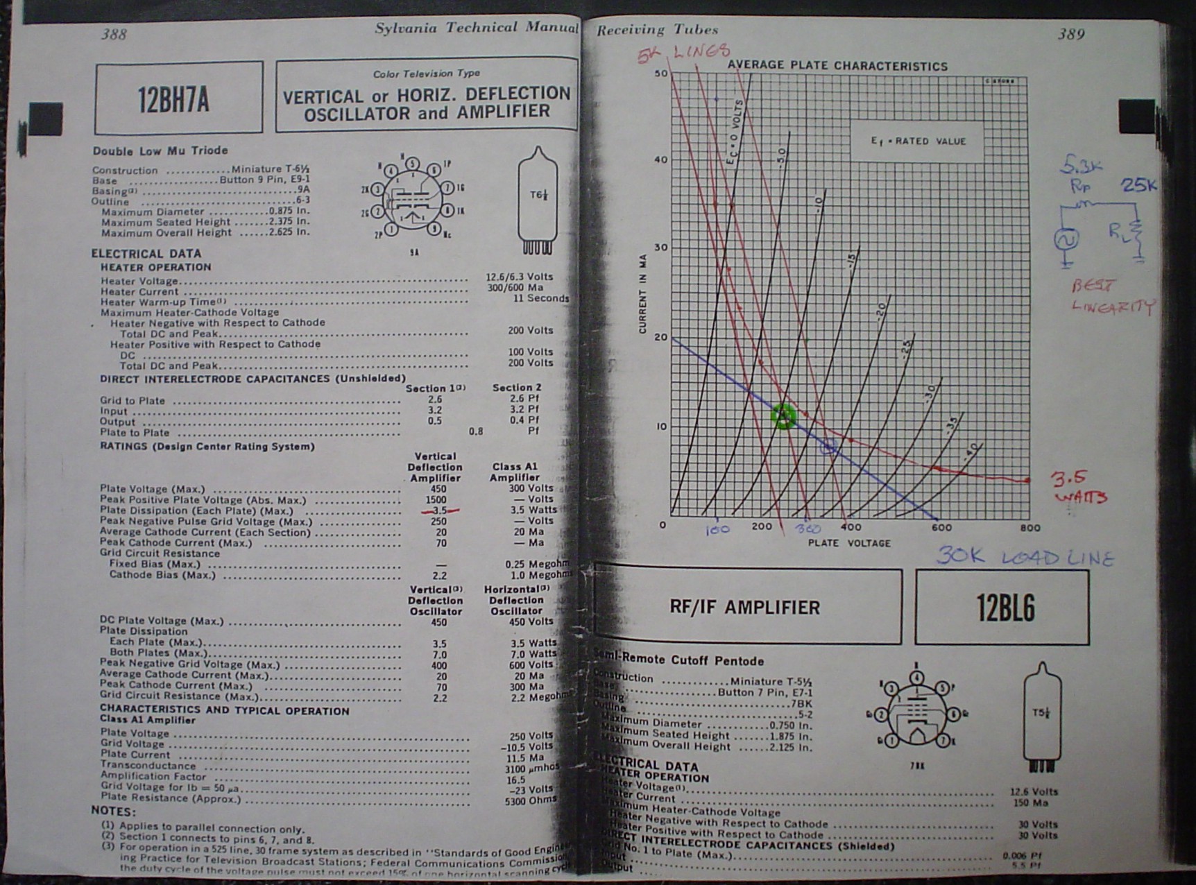
Some
people recommend using the 20A14 driver replacement transformer I
have as a step DOWN. This looks good on the surface to obtain a lower
drive impedance for the modulator grids for AB2. If you look at the
load line drawing on the tube characteristic curves I made, it shows
that the 12BH7 is out of limit on plate dissipation and nonlinear.
Hooked up as a step UP, it works correctly. I used feedback around
the audio system from the output of the driver to grids and sent it
back earlier in the audio chain just after the Low Pass Filter.
Inverse feedback (as noted in the incantation) results in the desired
low output impedance of the driver, which is essential to achieving
class AB2 which draws grid current in the 6146B. Again, a magic
incantation I learned from an ancient wizard: "Inverse feedback
reduces gain, noise, distortion and OUTPUT IMPEDANCE and raises input
impedance." Grid current can be drawn without excessive
distortion from the driver stage with the inverse feedback the way I
did it. Due to the low impedance of my design, I only needed 270K
swamping resistance across the secondary of the driver transformer.
Tim uses a lower resistance to load the stock driver transformer to
tame some of the nasty supersonic peak and swamp out the load
variations of the grid current. This replacement transformer is only
$25 and is commonly available from multiple distributors. This also
allows a push pull stage, eliminating second harmonic energy from the
driver distortion. The driver stage is the ONLY stage that uses a
cathode bypass capacitor. The low frequency response using a 1000 uF
capacitor across 2K is sufficient to pass even low frequency energy
from severe over adjustment of the clipper stage without canting of
the waveform. If you have a bigger capacitor to use for the cathode
bypass, go for it.
At the expense
of being concise, I included some thoughts on ideas that I discarded.
This is to save you the frustration of trying them out and finding
out they do not work, the same as I did.
Everyone has
their own solution; just because they differ does not mean that one
or more of the approaches is wrong. I appreciate them taking the time
to put their ideas out there to help others. They risk someone
disparaging their work when they do, but do it anyway. I present my
reasoning here, and the alternatives to my approach; you are free to
explore options. By explaining my methods, even if you do not do any
modifications, it may provide some ideas to begin your own work. I
hope you found something useful.
RECOMMENDED
READING:
- The Radio Handbook 15th Edition especially pages 300 and 301 on clippers and filters
- The Radiotron Designer's Handbook 4th Edition
- The Radio Amateur's Handbook 1954 Chapters 9 & 10
- WA1HLR's article on improving the Valiant
- W8JI's articles on Johnson transmitters
UPDATE 1-10-2014: W1CKI full audio chain distortion reduction feed back circuit
I have just run across the best inverse feedback circuit I have seen on the
web. It is a similar design to mine, uses the exact same driver
transformer, and tubes. I plan to implement a version of it to get even
better performance in the driver section as soon as I get a backup AM rig
running (Viking 2).
UPDATE 2-5-2014
I have been researching the "next step" feedback and found something at Electric Radio which has me rethinking the whole process. I am referring to Electric Radio #203 and #204, the April and May 2006 issues of Electric Radio magazine. You can obtain copies of back issues at http://www.ermag.com/.
This modification is by far the best I have seen. I wish I had seen it before I began this process. It would have changed the outcome. I am not disappointed with what I have now, and probably will just go ahead with the W1CKI component values for the inverse feedback addition to my mods. I am getting good reports now.
The mods articles are written by well known vintage transmitter expert Chuck Felton KD0ZS.
If you have not yet begun any work on your Valiant, I strongly encourage you to give his work a look before you even take the screws out of the cabinet.
Here are its features:
- Transformerless grid driver circuit. About the stock Valiant driver transformer, Chuck Felton states: "It is the worst thing you could have after a clipper; it's trash." You gotta love a man who calls it the way it is. However, it does not suffer the power limitations of the "East Coast" mods, since it is a low impedance driver. The 12BH7 driver for the 6146Bs is a cathode follower circuit.
- The clipper is retained for a modulation limiter to keep peaks from exceeding 100% negative.
- It can be configured so that the positive peaks can exceed 100%, using W8JI's suggestion of bypassing one diode with a capacitor.
- An overmodulation peak indicator is included in the design to allow adjustment of levels without having to have your scope on all the time. This will flash when you hit the baseline, telling you to back off just a tad.
- DC coupling is employed in some amplifier stages. Elimination of coupling capacitors extends low frequency response to zero Hz.
- A clever linear compressor keeps talk power up.
- Negative Feedback is applied around the modulation transformer, reducing distortion and improving bandwidth.
Basic improvements to the Valiant include:
- Bias circuit adjustment pot mods for better range of adjustment.
- T/R relay improvements
- Improved VFO stability on higher bands
- Front Panel mike jack, which is something I considered to reduce hum.
- A fix to prevent failure of the fixed loading capacitors.
|

