|
THE RF STAGE
AND POWER SUPPLY REGULATION
Low level and
driver stages, clipper and filter; inverse feedback
UPDATE 1/14/2017: "Johnson Viking Valiant Mods by WA1HLR & Using correct P-T156 or 124B Hammond transformer".
This web page is a blog about the process I used to make the E. F. Johnson Valiant into the transmitter I wanted it to be. I make no apologies whatsoever for its rambling nature. You may learn something from the engineering analysis and thought process, if you take the time to read it. This most certainly is NOT a one page, modification sheet. A radio of this complexity cannot be analyzed in one page. In ALL cases I have attempted to give credit to the sources I used to improve my Valiant. These authors include W8JI and WA1HLR. If I failed to note you as a source, please send me an email and I will credit you. I provide a link to the source material, so that you can decide if you want to use those ideas in your work. I got a LOT of questions on Timtron's work. I have photos and a schematic showing exactly how to do those mods. I do not rip off someone else's work. Accordingly, I have moved the part of my article employing the WA1HLR modifications (posted on amfone) to its own page: JohnsonValiant5.html.
There is a lot of confusion resulting from the choice of whether to keep the original Valiant audio configuration (single ended driver stage) with minor mods (W8JI and WA1HLR) or using the extensive mods PUSH PULL DRIVER STAGE contained on my site. I get a lot of inquiries about the WA1HLR Valiant mods; Tim provides a good written description of how to improve your Valiant. I used his mods and added my own. I provide in the link above, photos and schematics which include his mods, to clarify some ambiguities in the written information. I recommend you do ALL of the Johnson Valiant Modifications by WA1HLR FIRST; THEN replace the Johnson Valiant Driver Transformer with the P-T156 or P-T156 or the Hammond 124B. This will take you a LONG way. My full replacement with a push pull audio driver circuit is a huge job, and will make smaller but significant improvements, should you care to go to all the extra work, as a "level 2 modification".
WA1HLR says: "The anemic modulator has all it can do to reach 100% modulation. The audio quality is that of two dixie cups and a string." This is substantially the fault of the stock Johnson Valiant Audio Driver Transformer.
About the stock Johnson Valiant Driver Transformer, Chuck Felton, a well known professional restorer of classic equipment, states: "It is the worst thing you could have after a clipper; it's trash." You gotta love a man who calls it the way it is.
ADDITIONAL NOTE: If you want to do any of the mods like the W8JI or the TimTron mods and keep the single-ended stock 12AU7 paralleled configuration, consider the P-T156 or Hammond 124B.
The 124A is more like the original Valiant or other Johnson rig driver interstage,
but for the small increase in price, buy the 124B and get better than original performance.
The P-T156 works well, and only costs $16.
If your Ranger, Viking II, Valiant, or other Johnson Transmitter burns out an audio interstage transformer,
this is the replacement that works perfect and fits the original bolt hole pattern.
It also would be perfect for a DX100 or Heathkit Apache.
This is a true high fidelity transformer. Read the specs at:
http://www.hammondmfg.com/124.htm.
This section
continues the discussion of the Valiant modifications that I have
been working on for the last year. This discussion refers to the
schematics on this page showing the mods. I make no attempt to be
concise here, and ramble a lot about design details. Refer to the
original EFJ schematics and my drawings and photos as you read this
article. Skip the article and look at the schematics.
This
modification does not show on the front or above the chassis
and operates all components within manufacturer specs. It tunes up
the way the stock rig should as described in the original EFJ manual.
A trapezoid display of the modulation pattern is textbook perfect for
linearity when done. Largest cost item is the driver transformer,
which is about $25. Another mod transformer and 811s and other
blasting and drilling might provide marginally better performance,
but why not get a clean chassis and equipment rack and just start
over your way instead of modifying this rig?
I make
reference to other people's work in this article. I researched what
others were doing as I was developing my plan of action, just as you
are looking my ideas over. Nothing here is meant to denigrate their
designs. I looked at their choices, and made different choices for
myself. I offer the reasoning for why I departed from those prior
articles. It is not throwing rocks at someone else's work. Everyone
has their own solution; just because they differ does not mean that
one or more of the approaches is wrong. I present my reasoning here,
and the alternatives to my approach; you are free to explore options.
I hope you will find something useful.
The
parentage of my final version Valiant is as follows: nothing of the
"East Coast" mods survives. The RF stage, modulator
output stage, and VR tube modifications closely parallel the work of
WA1HLR as posted on line. We all owe Tim a lot both for the
information he shares freely with others as well as the preservation
of the art and science of classic AM radio. The fixes for flaws like
the drive pot also come from him. From the grids of the 6146
modulators to the line or mike input, I wanted a better driver
transformer, so all the rest of the design work is mine.
The three 6146s
in the RF stage are to be standard 6146s, not 6146B. These are
reserved for the modulator, as detailed in the first article
explaining why the Valiant strains to obtain sufficient audio power
to fully modulate the RF stage. How Johnson missed the correct
biasing of the RF finals is beyond me. Running three 6146Bs in the RF
deck does not provide a worthwhile increase in power and it DOES
increase the DC flowing in the modulation transformer for only 20%
more, not a good idea. You CAN run 6146Bs in the final at standard
6146 ratings. The neutralization and bias will work just fine, if you
follow the correct procedures in EFJ manual. You WILL benefit from
higher plate dissipation safety factor with the B version. Getting
full power from paralleled finals depends on good matching of the
tubes, and this gives you some wiggle room. As I note elsewhere, not
all radios tolerate this substitution well, especially compact SSB
radios. The 6146A has more emission and tolerates low filament
voltage better than the standard 6146, but has the same plate
dissipation specs.
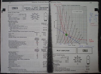
The design
shown here has about 8.2 mA per tube screen current at +180 V. This
is less than the EFJ design and is closer to the tube designer's
figures shown below. You may want to increase the screen resistor
more. This shows good trapezoid pattern and does not over stress the
6AQ5 clamper. The grid bias is obtained more from grid leak than the
original EFJ design, which makes better linearity in the RF stage
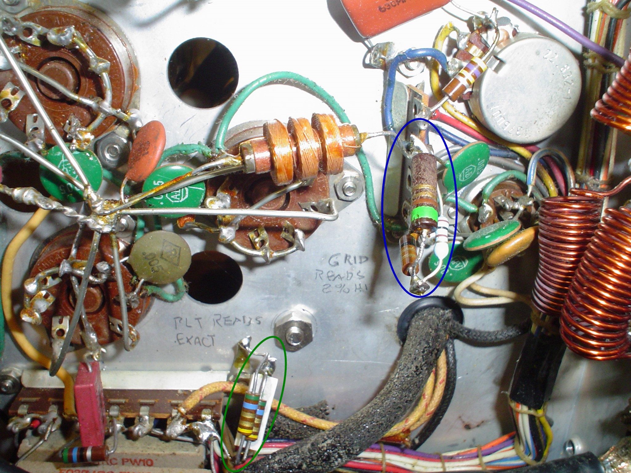
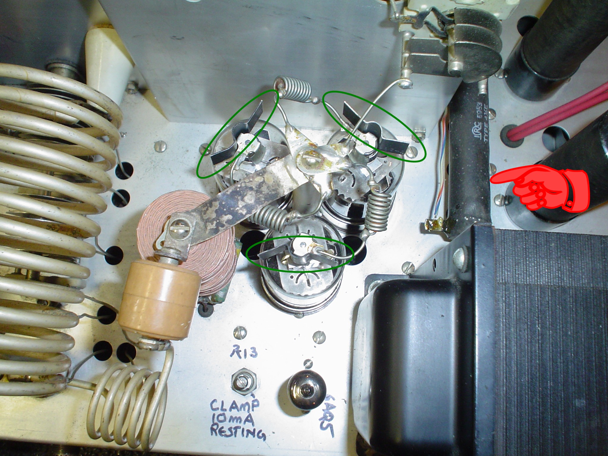
under modulation. It is critical to
note that the Valiant One calls for 50 mA resting current on the RF
finals in SSB mode. The Valiant 2 calls for 100 mA. WA1HLR recommends
100 mA per a conversation we had on the air. Use 100 mA as it is a
lower fixed bias voltage, allowing the grid leak resistor to do its
job properly.
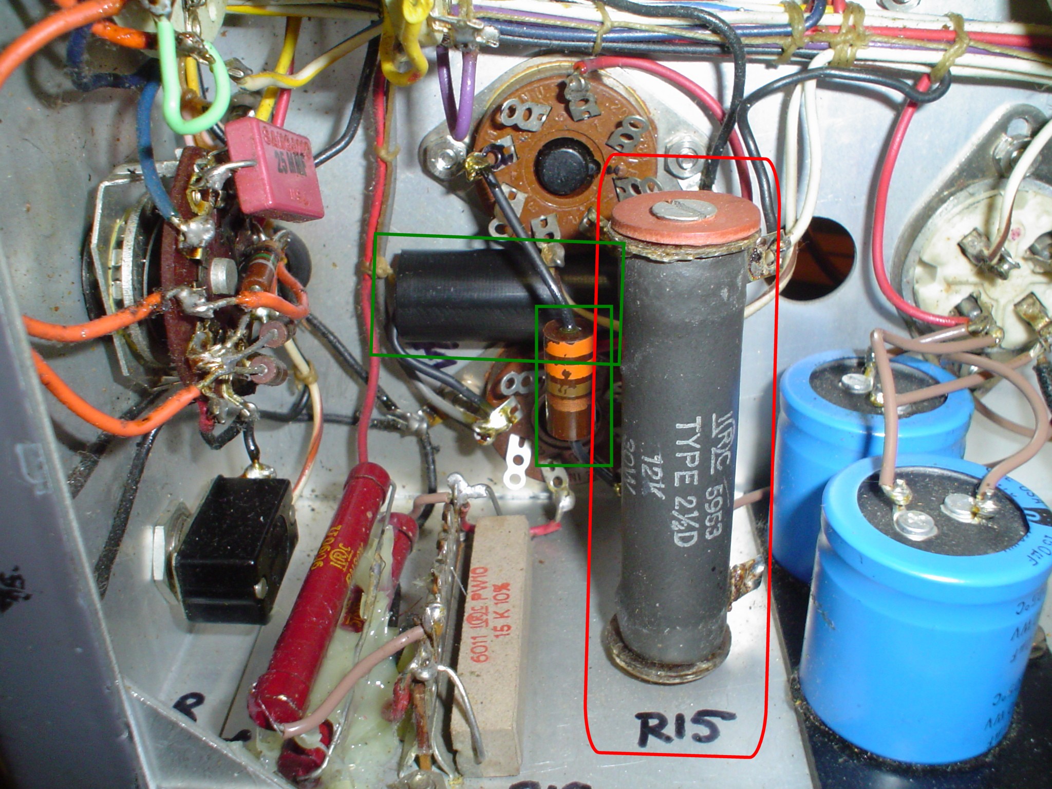
Click on thumbnails to enlarge.
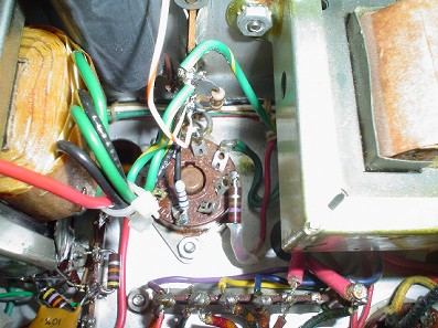
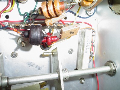
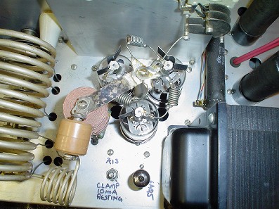
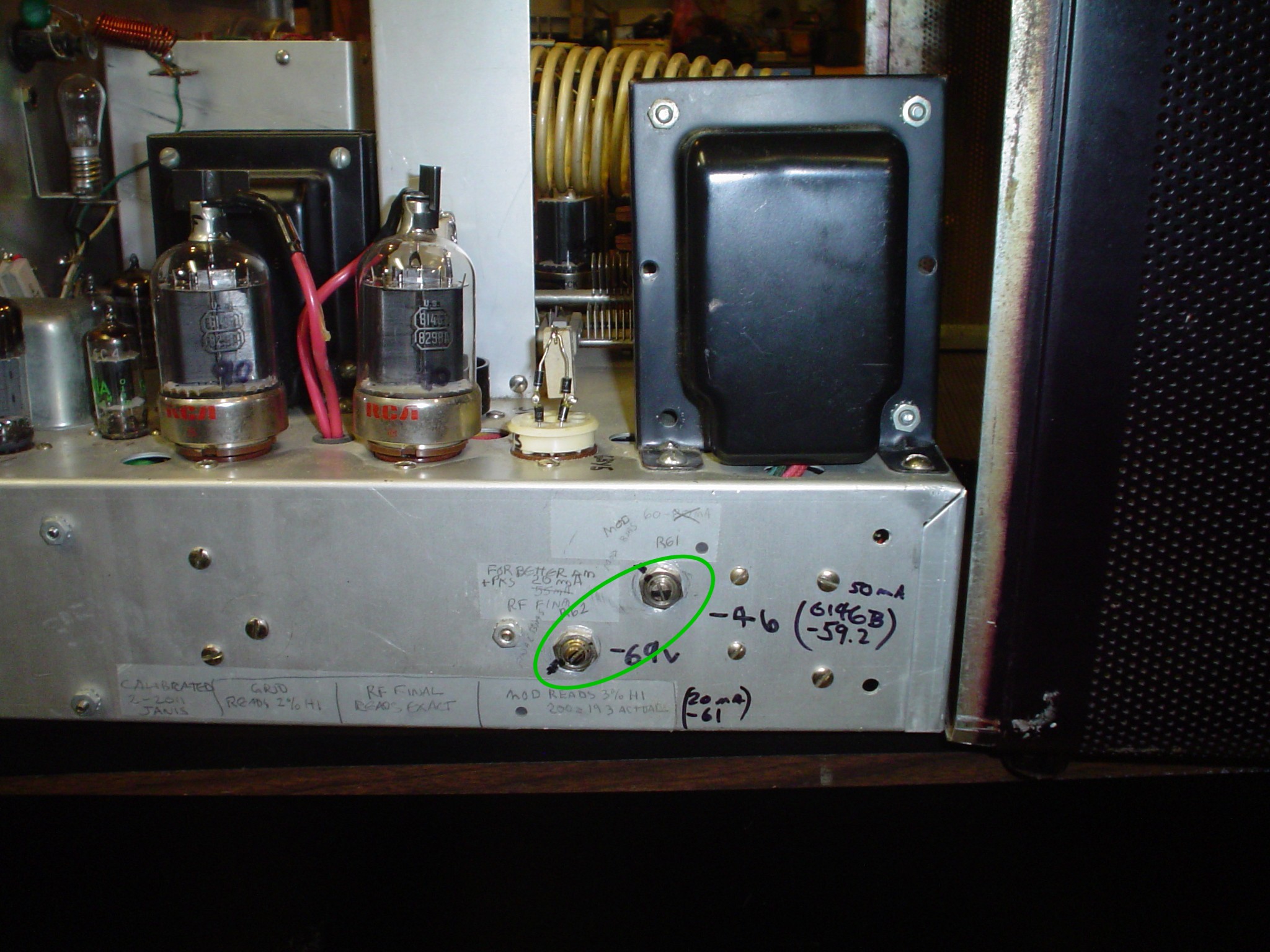
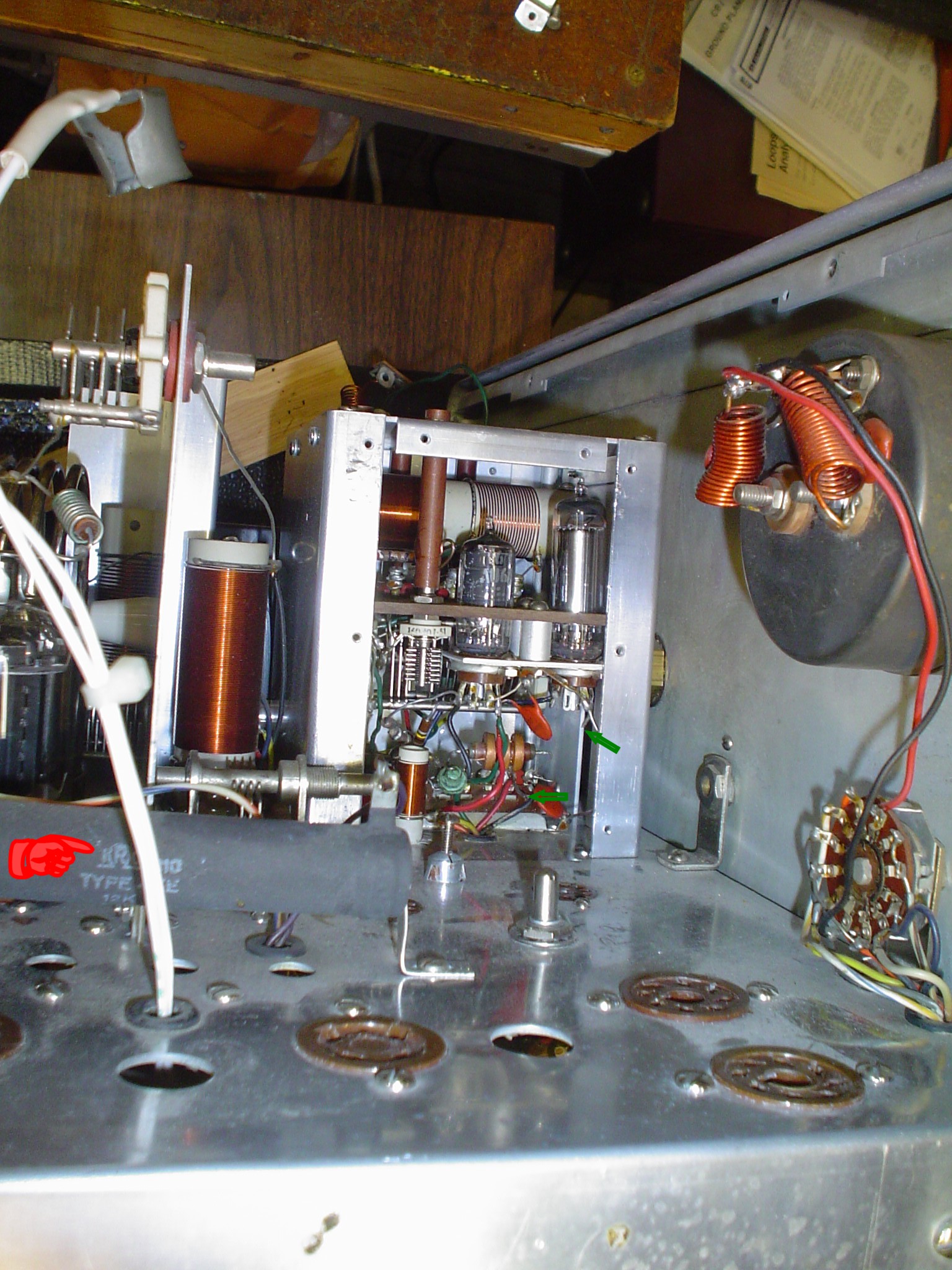
If you have not
done it yet, update the bias pots to the newer configuration, not the
old style slider power resistor style in the Valiant One. You can
drill small holes in the outer case to allow bias adjustment to
compensate for tube aging without removing the cover as shown above.
Use the online resources to compare the two configurations. I may
include a drawing on this page also. Updating it is not difficult at
all. I adjust Resting Modulator current to 55 to 60 mA. I found the
80 mA figure does not measurably help with linearity and only causes
unnecessary heat and stress on the 6146Bs. Others differ and say to
run them hot. I try to keep things as cool as possible so that if the
current drifts up, I do not have to take immediate action to prevent
China Syndrome.
Intermittent
Commercial and Amateur Service (ICAS ratings) PER TUBE. Multiply by 3
to get the Valiant Numbers.
STANDARD
6146 OR 6146A SPECIFICATIONS (Class C Plate Modulated Telephony)
GE
TRANSMITTING TUBE MANUAL, 1955 Radio Amateur's Handbook, RCA TT-5
Plate
Voltage: 600
Screen
Voltage: 150 (Maximum screen power 2 or 3 W depending on who you
ask).
Grid
Voltage: -87 (Some hams like -100 to -120V)
Plate
Current: 112.5 mA
Screen
Current: 7.8 mA to 12 mA
Grid
Current: 3.4 mA EFJ says 3.0 mA, which I use. ( CCS says do not
exceed 3.5 max in RCA TT-5 manual. ICAS says DO NOT EVER EXCEED 4
MA!)
I
PERSONALLY RECOMMEND OPERATING GRID CURRENT AT WELL BELOW ICAS AT 3
MA PER TUBE OR 9 MA ON THE VALIANT FOR LONG TUBE LIFE.
Plate
input power: 67.5 W Max
Power
Output: 52 W approx.
Efficiency: 77%
Timtron
attributes premature tube failure to excessive SCREEN grid current
and wattage. The EFJ design seems to push the limit on this.
W8JI
makes no observation on this point. He does not specify the resting
current setting and uses a 10K grid leak resistor.
The
tube handbook maximum grid leak resistor is 27K for class C stages.
My
experience has been that a higher value of grid leak resistor is less
tolerant of 6146s that exhibit negative grid current in standby.
I
found Tim's approach to achieve the best balance between good
linearity and tube life, and follow it generally here.
Excessive
grid drive or plate dissipation from off resonance operation and the
like eventually results in the grid meter deflecting below zero when
in the CW mode and unkeyed with the plate voltage applied. Once this
occurs, the 6146 has been irreparably damaged.
You
might be able to get some more use from it in an application that has
very low grid circuit resistance, such as the modulator. I have not
verified if they are OK in this case. The abuse of tubes does not
result in either worthwhile S meter readings or marginal audio
improvements on receive.
Adjust
RF plate resting current to 100 mA in SSB. Adjust clamper per EFJ
manual.
Tune
up in CW for:
3
X 3 = 8.5 to 9 mA grid MAXIMUM. NEVER EXCEED 12 MA!!!!
3 X 110 mA =
330 mA plate
Plate voltage
about 630 V in Valiant. Remember the screen current is included in
the displayed plate current as measured in the Valiant since it is
Cathode current.
This is
conservative and allows a little wiggle room for mismatched 6146s in
the RF stage.
Approximate RF
output power is measured at 150 W as EFJ specifies. I experienced no
loss of power from raising the screen resistor value.
Modulator
resting current set to 55 to 60 mA. Peak modulation may peg the meter
now due to increased power. Average may run 165 mA. But use a scope.
Your neighbors on the band will appreciate it.
MODULATOR
OUTPUT STAGE CONSIDERATIONS
VERY VERY
IMPORTANT!!! DO NOT TEST THE MODULATOR FOR EXTENDED PERIODS AT FULL
OUTPUT! Use a signal that keeps the modulator plate meter below 100
to 125 mA. The tubes and other components are not designed for
continuous sine wave output at maximum levels. The
modulator will operate perfectly safely with normal speech waveforms,
even with heavy compression or clipping. You can run frequency
response curves at lower levels and still get good data. If you run
high level tests, such as 100% modulation tests with a trapezoid
pattern, limit them to a few seconds maximum, and allow adequate time
for cooling. If at any time, any of the plates of the 6146s show any
color, STOP IMMEDIATELY.
The
example you may be familiar with is that of, say, an Ameritron AL811.
You may safely operate it at 500 watts on intermittent waveforms. You
must reduce drive till the output falls off if you intend to use it
in RTTY or full carrier AM. This precaution is of the same nature, to
observe the AVERAGE power restrictions.
NEVER
operate the modulator power
stage without the RF power amplifier operating and properly tuned.
The RF stage is a resistive load to the modulator and without it, the
modulation transformer will be instantly destroyed. Most people are
used to integrated AM rigs with all the necessary circuitry supplied.
In the instance of an Eico 720 transmitter and 730 modulator, two
separate units, the mod transformer sometimes is destroyed by people
unaware of this precaution.
I
include these warnings to those who might be new to the AM technology
to apprise them of the fundamentals, so that they may avoid hard
lessons.
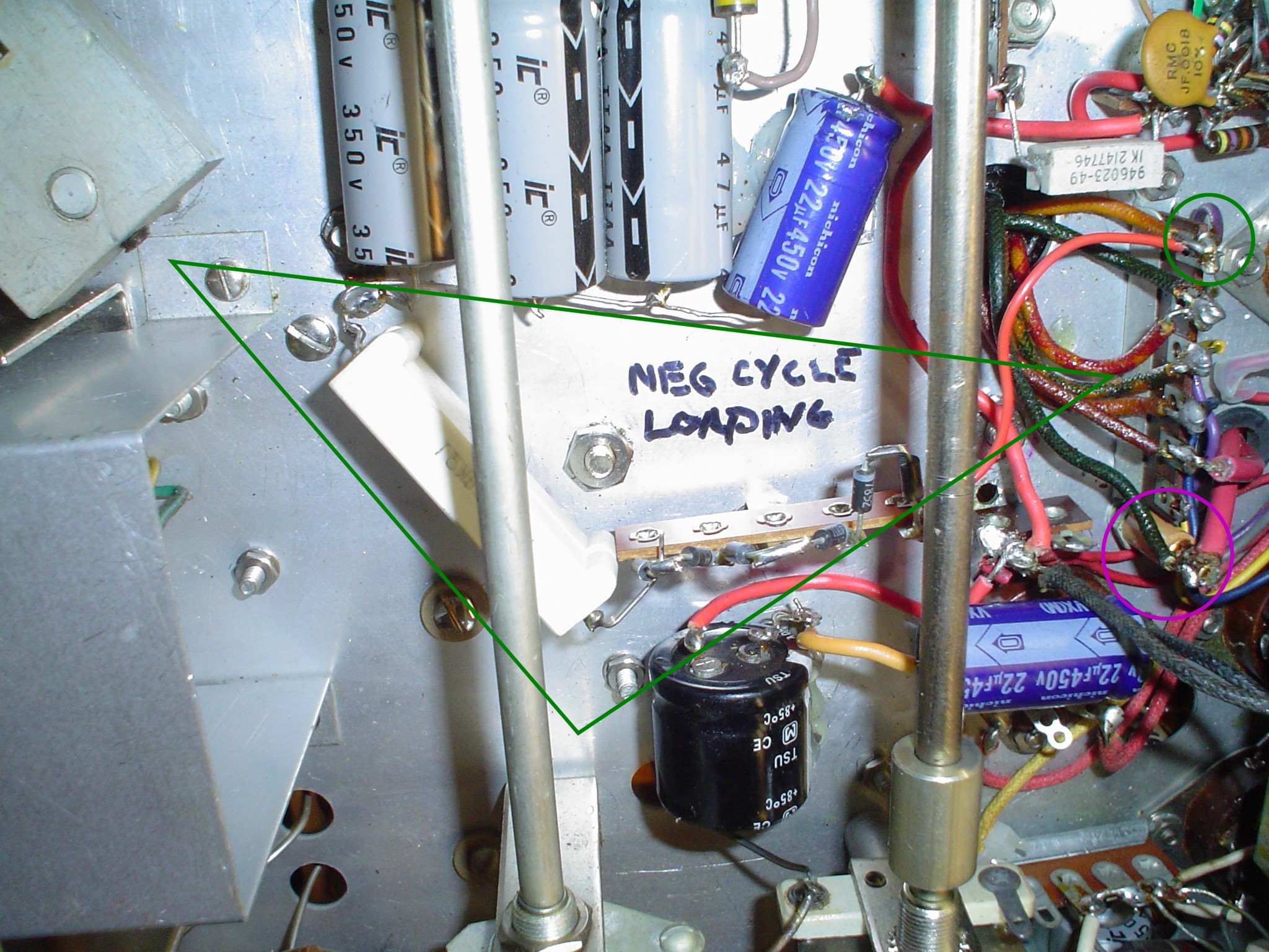
I added
negative cycle loading. The modulator originally did not develop
enough power to endanger the modulation transformer by forcing the
level to exceed 0% negative peaks. Now the transformer may drive the
final to less than zero volts on the plate, causing it to shut down
(its a diode for this purpose). Without the approximate 2K load of
the RF final, voltages soar and the modulator transformer or
components may arc. The rig I have originally DID arc to the point
that it required an extra set of standoffs to attach the transformer
leads with sufficient insulation. The negative cycle loading consists
of sufficient 1N4007 diodes (for Peak Inverse Voltage Rating) and a
2K resistor which is switched in by them to continue loading the
transformer. See the arcs and sparks discussion I posted.
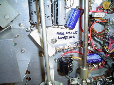
Click on thumbnail to enlarge.
I had a whole
discussion of high level splatter filtering that I removed from this
article. It may be a separate article in the future. There are lots
of risks to the components of the Valiant by messing around with this
technique. There is a technique to testing frequency response of mod
transformers or splatter filters at low levels with resistive loads
to simulate the tubes. I got what I wanted without using a high level
splatter filter.
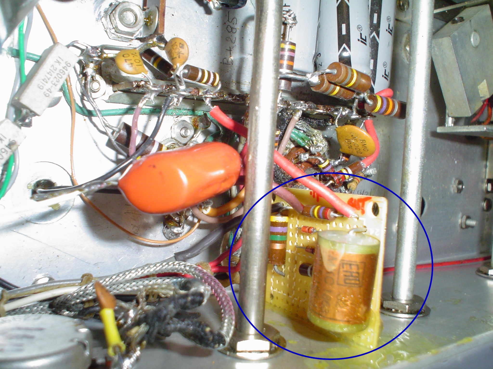
The low level
clipper can be built out of more common parts. If you mess up the
design, it probably won't destroy anything. It still limits splatter,
a good thing. You do not constantly have to ride the gain and stare
at the scope to keep your audio from hitting the baseline. The
mistake people make employing the clipper is to run it at 25 dB
clipping to obtain more punch. What they get is fuzzy distorted hard
to understand audio. Using 3 to 6 dB will not be noticed. Properly
adjusted, the clipper prevents splatter. The LC filter in a pi
network configuration blocks harmonics generated during clipping and
undesired high frequencies from passing to the power stage. This
prevents excessive bandwidth. Even the external audio chain in my
design enters before the LC filter. In the microphone input
amplifier, a small capacitor across the level control and a small
capacitor across the phase inverter aid in the suppression of
excessive bandwidth. Additional shunt capacitance is across the
modulation transformer to limit excessive bandwidth, as discussed in
this article. It is shown on the schematics.
If you wish to
omit the clipper or even the filter, I have provided points on the
drawing where the deletion of the undesired components and the use of
an appropriate coupling capacitor will get you to the version YOU
want. What you will wind up with is a transmitter that has the RF
final biased correctly, and a real class AB2 modulator with a low
distortion driver that will do about 50 Hz to 8 KHz if you remove the
band limiting components. I leave it to you to customize the final
product to your preference. You might be able to eliminate the extra
6AV6 also. I will leave that up to you. To connect the mike preamp
stages (12AX7) to the driver stage directly, attach point "X"
to point "A" or "B" with a capacitor and
resistor of appropriate value and rating. If you remove the clipper,
you can use the front panel clipping control for a level control for
the outboard audio from the line input, if you wish. The capacitor
should be selected for appropriate low frequency response. The series
resistor should be selected to avoid over driving the following
stages. I have provided approximate AC and DC voltages on the
schematic for guidance. These levels were obtained with the front
panel controls set for nominal correct operation: about 9 o'clock for
audio and full clockwise for the clipping to avoid interaction during
testing. In operation, it will be about 10 o'clock with the resistor
values shown. Use a scope to set it properly.
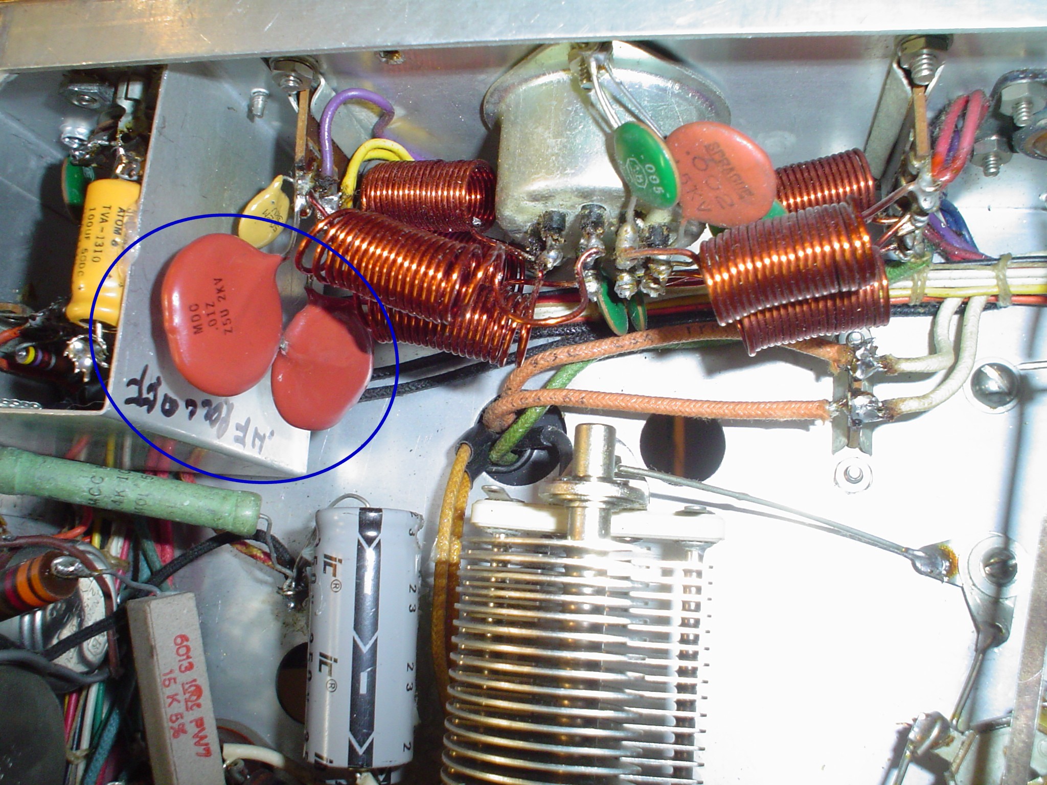
I mounted the upper
frequency limiting capacitors near J8 on an existing terminal strip.
That way it is easy to swap values as you do performance tests. You
might want to put them inside the J8 mating plug, so that you can
switch them around for varying operating conditions. This capacitor
"builds out" the modulation transformer as is commonly
done in those days. NOTE: high voltage is present on J8; use good
construction techniques and for safety sake, be sure that the metal
cap on the plug is insulated from all wiring and components. I may
post something that shows how to do select capacitors to "build
out" the mod transformer without having high voltage on the
transformer. But it is in the 1950s handbooks, if you wish to
research that.
Click on thumbnail to enlarge.
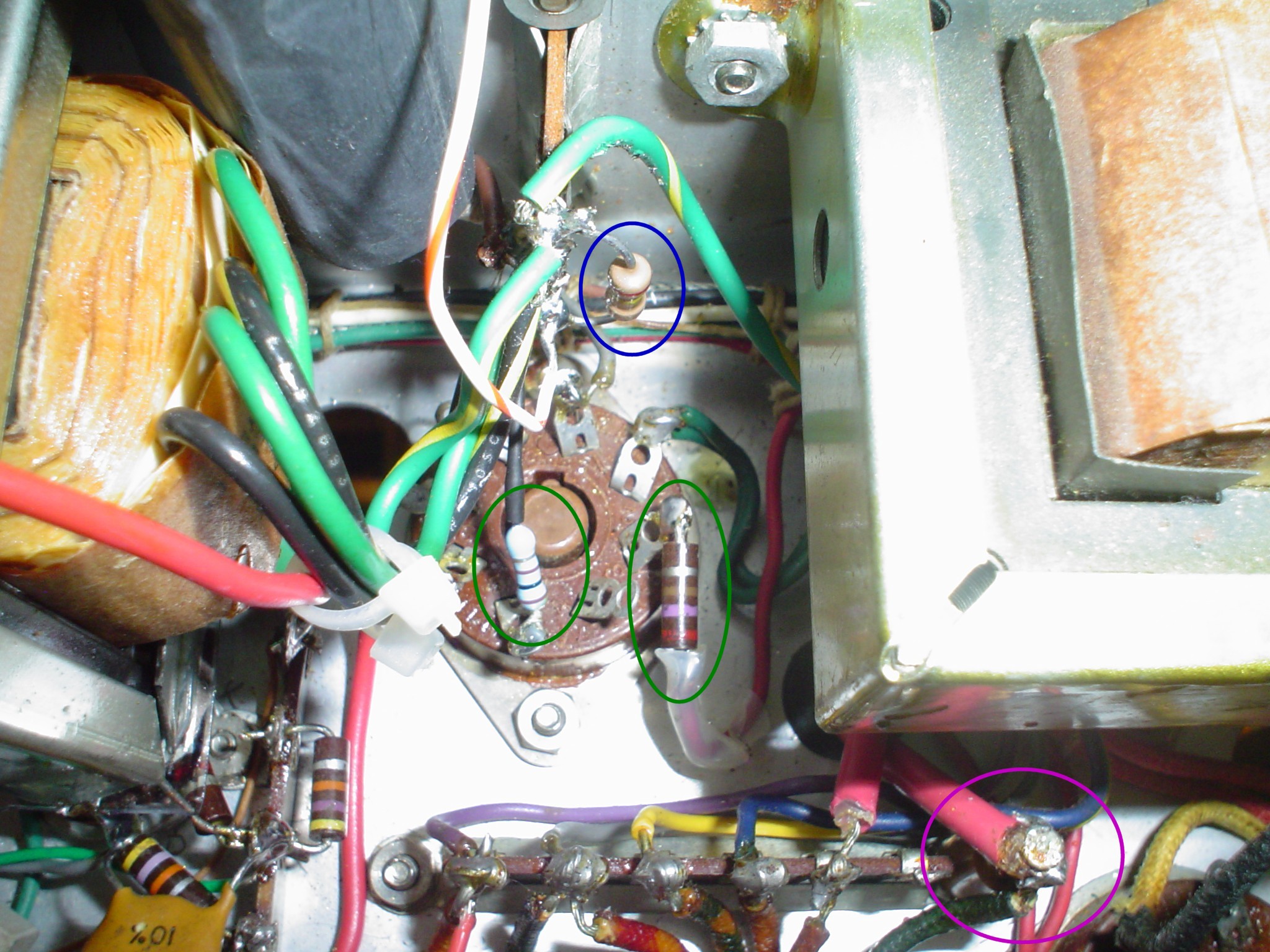
The terminal
strip that wires to the mod transformer are shown below for your use.
This information is not directly in the Valiant manual; it takes a
while to dig it out and verify it. You will need it if you are
testing the transformer with power off. Unplug the tubes and use the
6146 plate caps with a signal generator and a simulated plate
impedance resistor(s), driving it push pull with a center tap to
chassis ground to keep things modeled properly. Unplug J8 and monitor
the output with a proper low power resistive load (about 2K or 630
volts divided by 330 mA) to simulate the RF stage. Adjust the
capacitor values and sweep the frequency to observe the effect of the
test values on the terminal strip nearest J8. Be sure to account for
the capacitors in the other side of J8 and in the RF stage near the
big plate RF choke in the final compartment. There is no risk to the
components or safety hazard by doing this "power off"
testing. Once you have settled on a value that does not generate
unwanted resonance peaks that might damage things, solder the test
capacitor on the terminal strip and reassemble things and do a "power
on" test to verify your work. Use a scope as well as a receiver
with a narrow filter to check your splatter while transmitting into a
dummy load. The original EFJ values are totally safe. I opened it up
very slightly but did not exceed 3500 cycles. I do not recommend
values that are smaller than those on my schematics or in Tim's
article.
The first entry
is the terminal nearest the front panel. The last entry is the
terminal nearest the back panel.
Yellow to RF
plates
Red-Yellow and
Green sort of center tap of transformer to J8 (to use Valiant to
drive an external modulator grids)
Green-Yellow to
HV B+ via J8
Red to Modulator HV B+
Brown to Modulator Plate
Blue to other Modulator
Plate
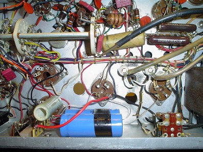
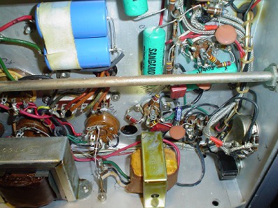
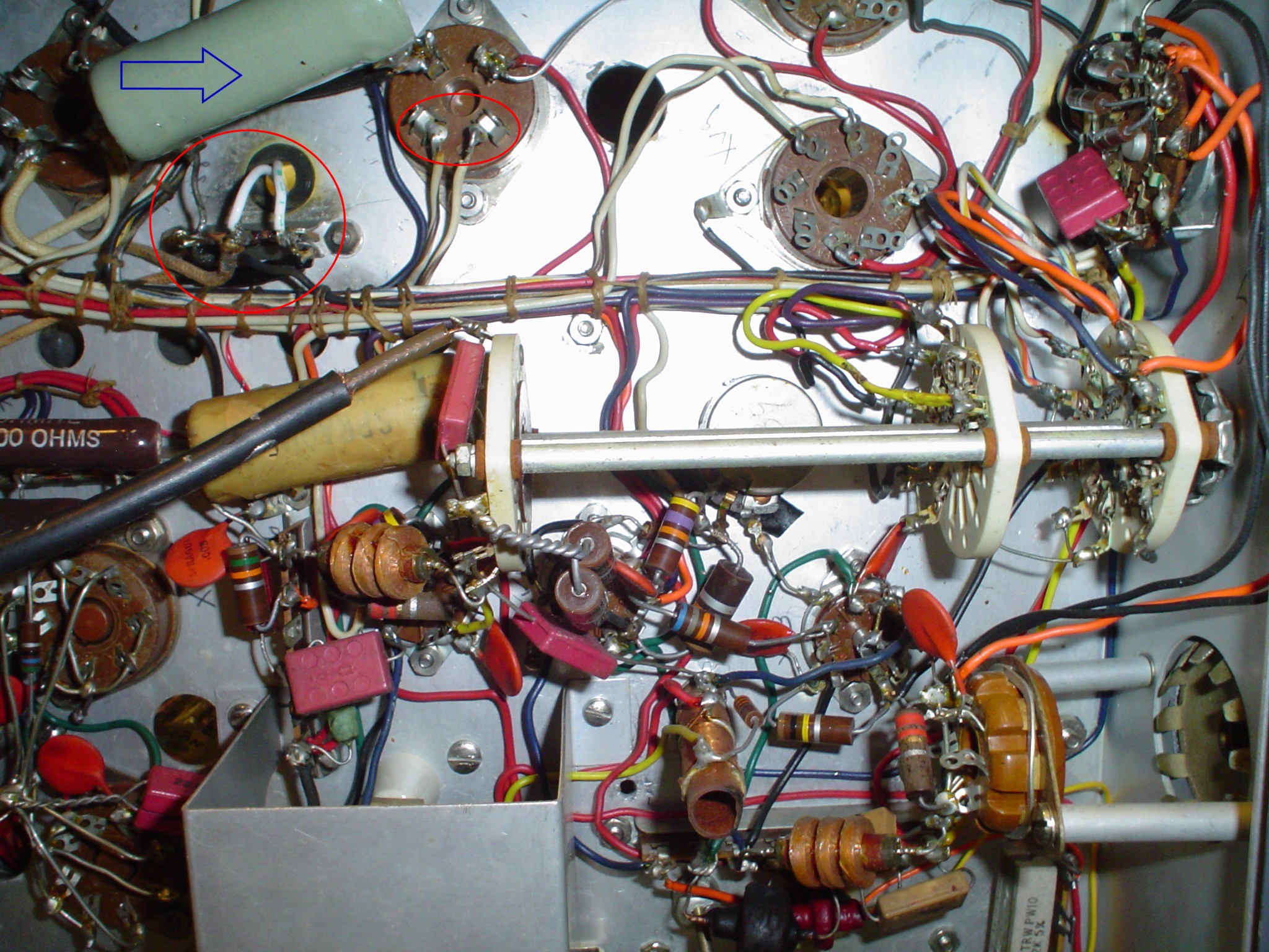
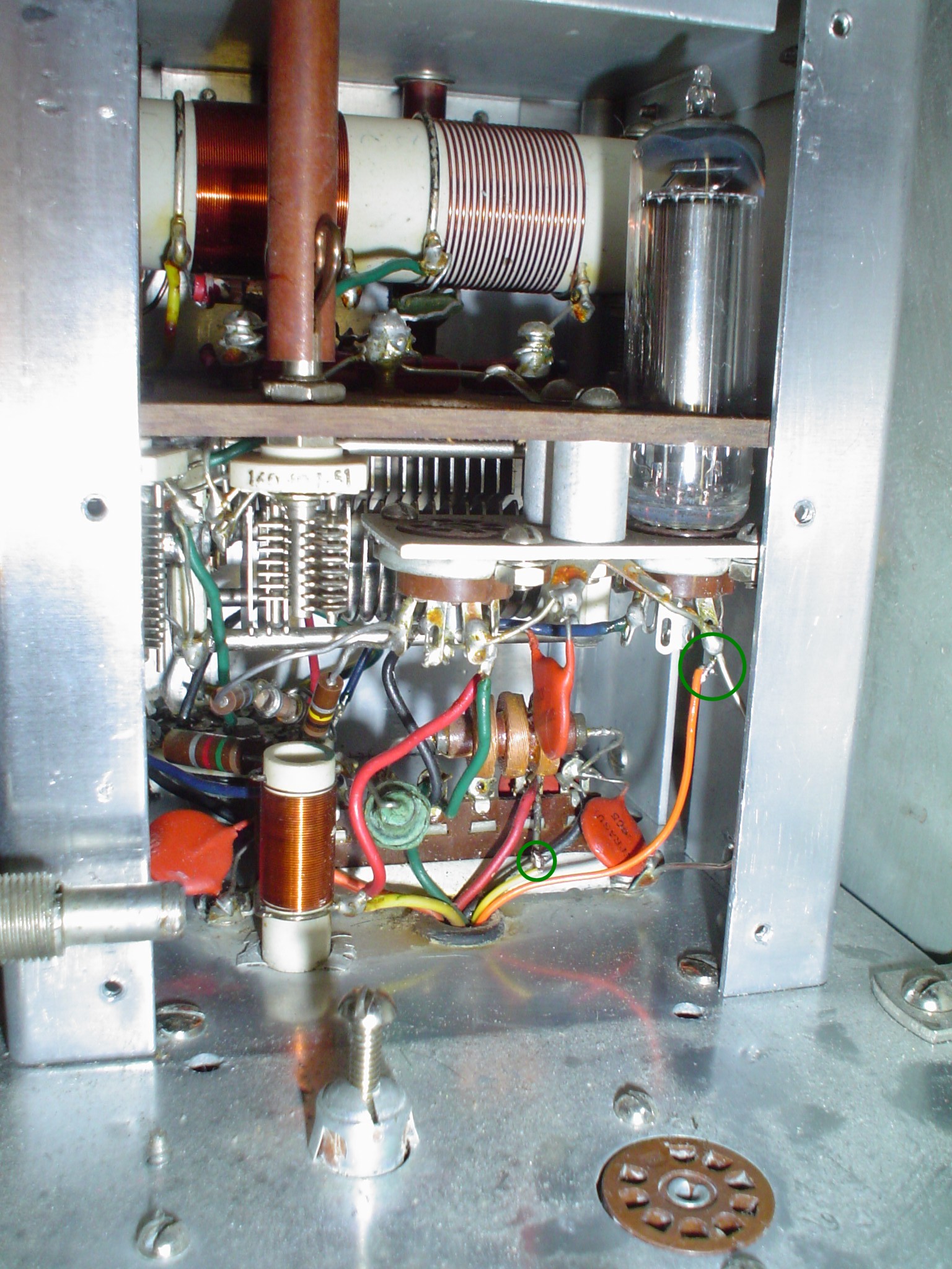
The 6146B
modulator screens need a series resistor of about 270 ohms and
changes to the regulator tubes to reduce audio energy present at the
screen. There is a 10 to 20 uF capacitor to stabilize the screen
voltage and a 330 ohm resistor to prevent the VR tubes from
motorboating in and out of ignition (called relaxation oscillation).
I adopted this fix and found it reduced distortion at drive levels in
excess of 70% modulation just as he said. See the schematics for the
wiring details. See the photos for the mechanical details. This is a
key modification that is absolutely essential to the proper operation
of the whole system described in this article.
click on thumbnails to enlarge.
PROBLEMS
WITH ARCS AND SPARKS
This problem is
why I did not do the extra mods in the "East Coast"
version to increase the modulator B+ to 1000V. Perhaps if I had done
those mods and they worked without flashing over, I would never have
gone this route. As is stated in WA1HLR's article, you have to do the
whole set of modifications in any article to get the performance
increase expected; half way just does not cut it. I failed to do that
in the case of the “East Coast” mods and did not get 100%
modulation without distortion. Maybe you can get a HiPot tester on
loan from a friendly electrician to determine if your rig will
tolerate the higher B+. Of the five Valiants that have crossed my
workbench, none of them appeared up to the task.
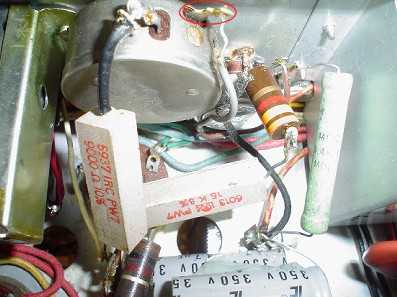
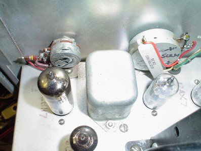
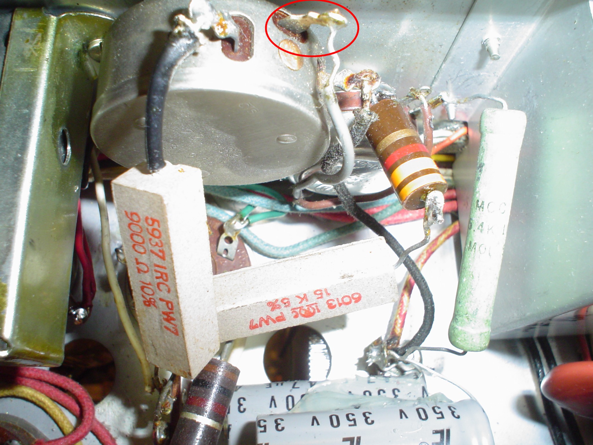
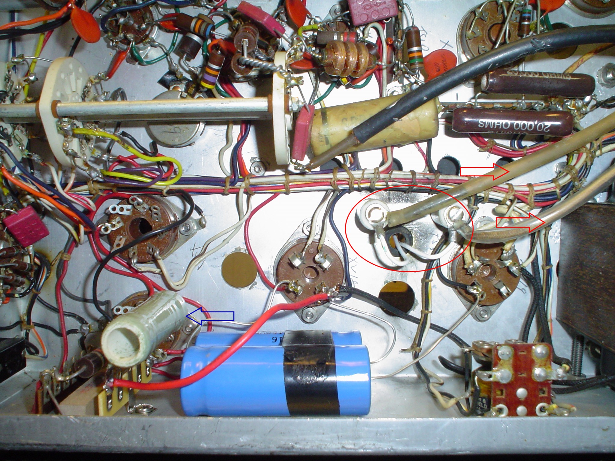
Here is why the
high voltage power supply has problems with the 866 filament wiring
and high voltage choke wiring.

click on thumbnails to enlarge.
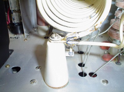
Even the
terminal strip for the modulator windings can arc. This shows an
added standoff to correct that situation.
click on thumbnail to enlarge.
Take a look at
the separate article with pictures of the previous damage inside an
unmodified Valiant, and you will understand why I did not proceed
with mods posted on the net. People have done the “East Coast”
mods successfully with the high B+ mod implemented and experienced no
problems, so decide for yourself what you want to do with your radio.
Inspect carefully for any arc points in the radio before doing any
mods. I include pics of arcing on the terminal strip for the
filaments of the 866. Also, the wiring for the HV plate filter choke
are insulated with additional sleeving. There is another terminal
strip near the LV fuse for the 866 filaments which can cause trouble.
Sleeving may be required on the 2.5 VAC filament wires into the LV
transformer. The 4 pin sockets may arc. (The Viking 2 is notorious
for this, and all that is required is to put insulating spacers and ¼
inch longer mounting screws on the sockets for the 5R4s.) Replace the
866s with 3B28 tubes to avoid mercury warmup issues with resulting
flashover upon application of HV power. I have commercial solid state
replacements in my rig. The modulator transformer terminal strip is a
possible problem. Ceramic standoffs help. The back panel jumper
connector J8 is a possible problem. All these potential problems are
the reason I did not attempt the “East Coast” mods that
raise the HV B+ to 1000 V on the modulator.
Some people
have had success with this approach, but looking at the wiring
harness and all these known failure points, I sought another
solution. This one worked out OK for me. Look it over, and see if it
will work for you. A new $25 driver transformer goes a long way
toward improved performance. This one makes full modulation and
decent frequency response without exceeding ICAS tube ratings or
risking failure of old wiring due to “hot rodding” the HV
power supply.
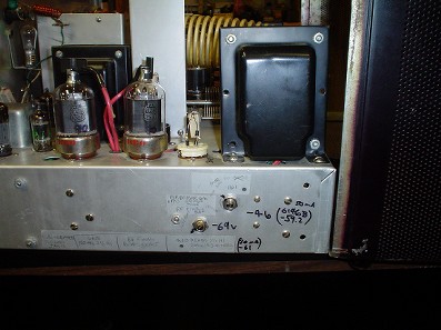
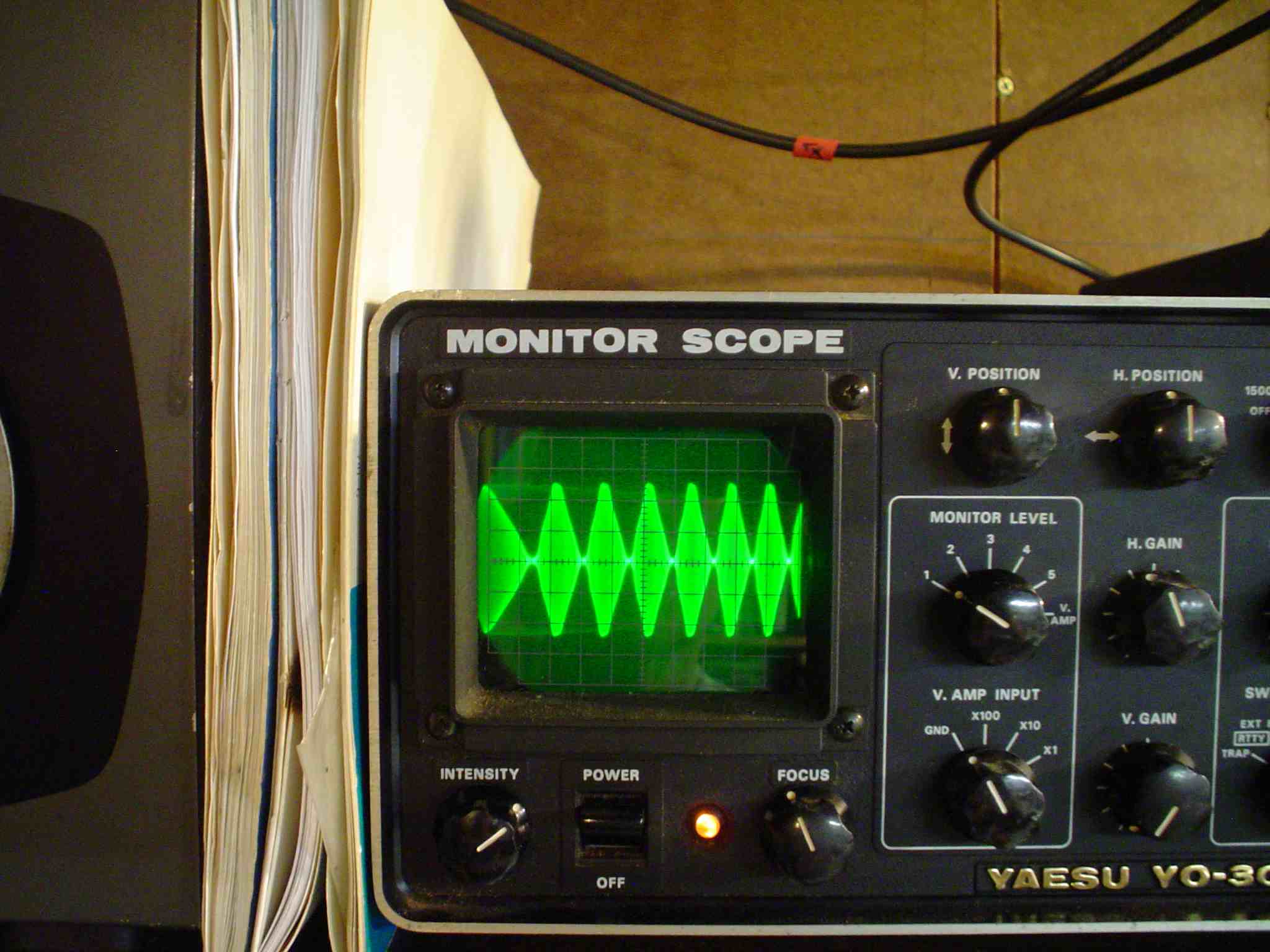
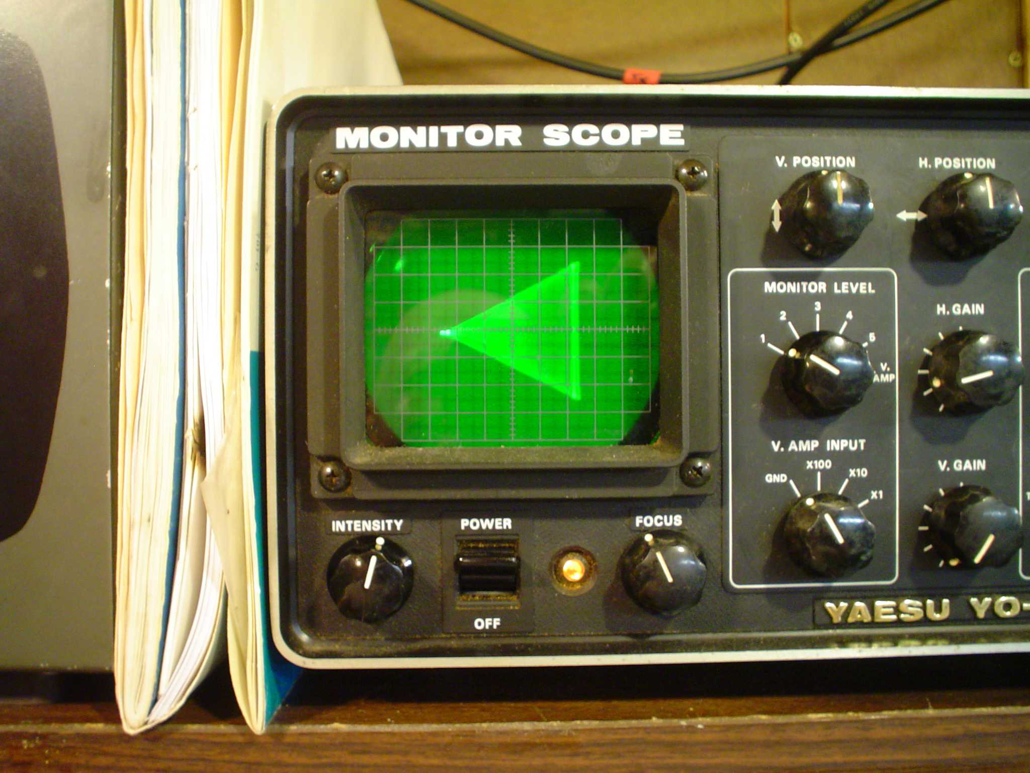
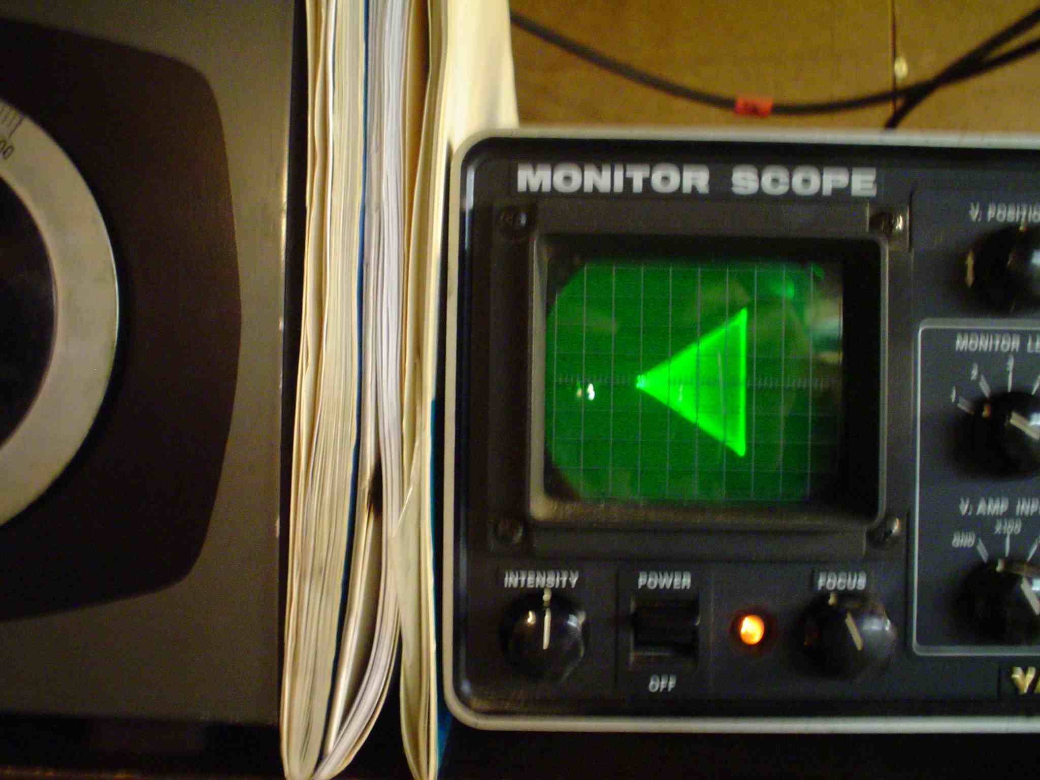
INSTRUMENTATION IDEAS
I added a
sample point for the modulated B+ to feed the horizontal deflection
of my monitor scope. This allows the RF to be on the vertical
deflection for a trapezoid pattern as shown in some of the 50s
handbooks. At the completion of these modifications, I got a perfect
textbook pattern. It is a lot easier to judge a straight line on the
side of a triangle than guessing at a peak of a speech pattern for
linearity. You can strive for linearity in the audio system and fail
to get the RF biasing correct and wind up with distortion that is
hard for a receiving station to characterize. Circuit constants shown
are good to below 100 Hz for the sample circuit. The modulated high
voltage sample comes out to an RCA jack just below the SSB jack. Its
hard to find a spot to mount anything on the back apron without
ruining a harness. All my instrumentation is located here. Before you
add a trapezoid test point, be sure to read all the article here
about it and observe proper electrical safety procedures to avoid
equipment damage and shock hazard. If you do not have training or
experience with tubes and high voltage, do not attempt any of the
modifications described here.
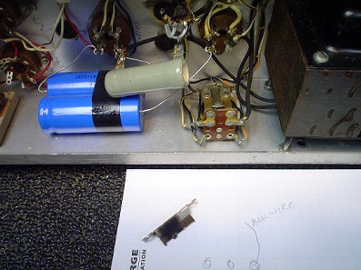
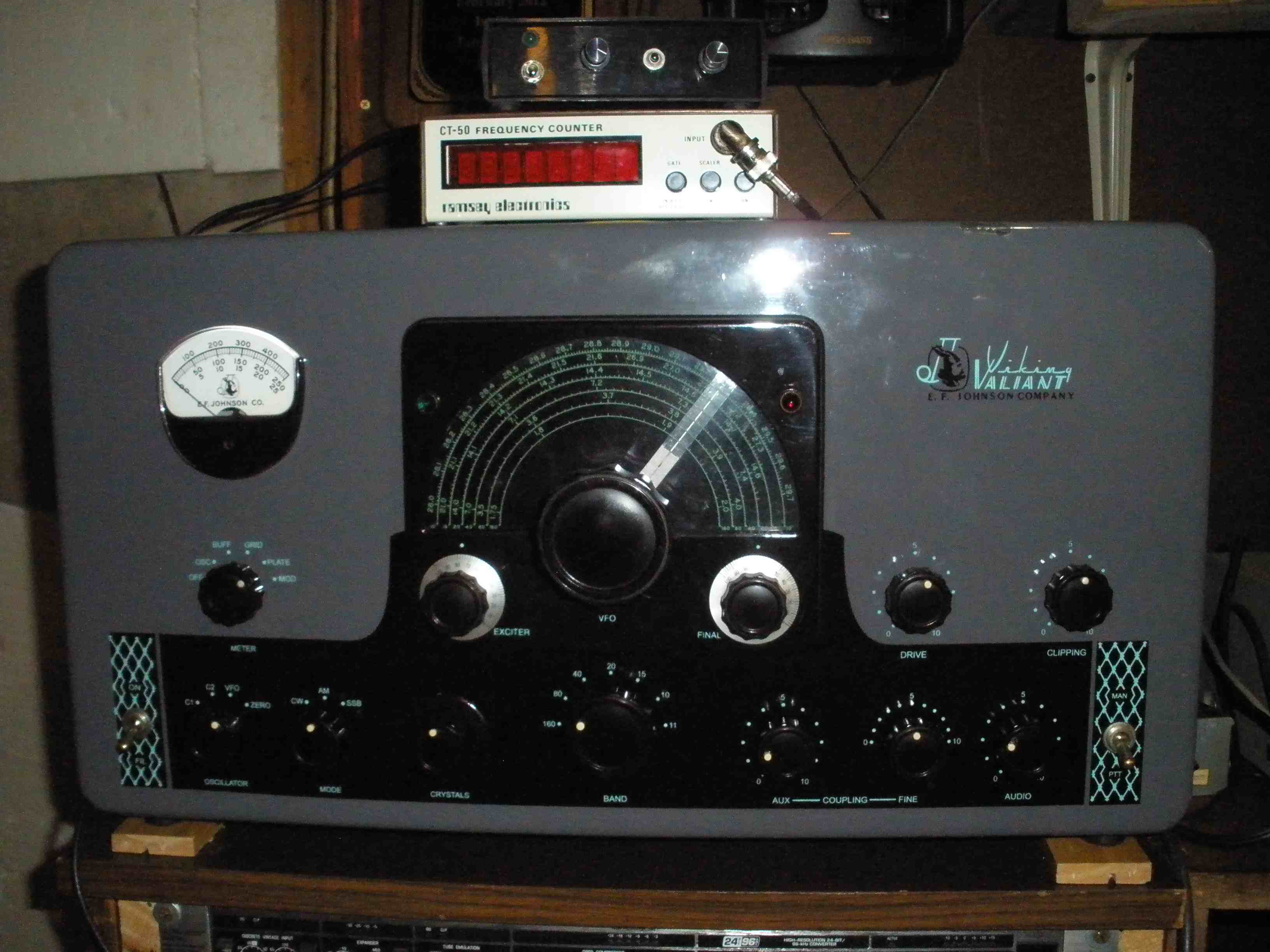
I disconnected
the SSB drive input wire from S4 and the 100 ohm resistors and placed
the loose wire end near the grid tank coils. Insulate the end and
anchor it with tie wraps so it does not short into anything. I
connect an external frequency counter to the back panel jack to spot
on frequency with this signal without actually putting a signal on
the air.
You will see in
the photos that I have not retained the original meter shunts. I
began my career in a calibration lab. So I check and often remove or
trim the values of the original shunts if they are not accurate to
5%. The wire shunts EFJ uses do not lend themselves to calibration
well, and are nearly impossible to solder to. Copious amounts of flux
and heat are required. Generally they are way off calibration. My rig
on RF plate was over 20% off. The Grid meter reading was also way off
calibration. Due to the common availability of accurate low value
resistors these days, I have no reservation about hacking these out
and ditching them for better calibration. It is very difficult to
directly measure the low ohm resistors. The end result of accurate
current readings is easy to achieve without specialized four lead ohm
meters. I was unable to convince a friend to do it this way after
lengthy discussion. I suspect he got inferior results and wasted much
time the other way. A small variable supply or 12 volt supply and
variable resistor are all that is needed to get the panel meter to 1%
if you wish using a modern digital meter. These tests are done with
the Valiant unplugged from the AC power. Simulate the current in the
circuit with a power supply with a digital milliameter and current
limiting resistor in the lead and observe the panel meter. The
Valiant should be in the normal horizontal position to avoid gravity
effects on the Valiant panel meter. This is really important to do
before you attempt any modifications. Think about it. If your plate
meter reads high, and your output power is low, are you really
running rated input power? Bad data does not help you tune up your
rig properly.

click on thumbnail to enlarge.
If the panel
meter reads lower than the digital meter used to calibrate it, a
resistor must be inserted in series with the multiplier resistor in
the Valiant. This is pretty straightforward. Increase the value of
the Valiant resistor by 1% if it reads 1% low.
If the meter
reads higher than the digital calibration meter, a shunt resistor is
required across the existing resistor to reduce its value.
Here are some
helpful rule of thumb approximations if the meter reads high:
If the meter
reads 20% high, put a shunt resistor across the multiplier resistor 5
times the value of the multiplier resistor and the panel meter.
If the meter reads 10% high,
put a shunt resistor across the multiplier resistor 10 times the
value of the multiplier resistor and the panel meter.
If the meter reads 5% high,
put a shunt resistor across the multiplier resistor 20 times the
value of the multiplier resistor and the panel meter.
If the meter reads 2% high,
put a shunt resistor across the multiplier resistor 50 times the
value of the multiplier resistor and the panel meter.
If the meter reads 1% high,
put a shunt resistor across the multiplier resistor 100 times the
value of the multiplier resistor and the panel meter.
This process can be done
repetitively to approach the value with higher and higher shunt
calibration resistors until you get as close as you wish.
If you need to fix the RF
plate or Modulator multiplier resistors, the best way is to hack out
the original resistance wire loop and replace them with a real
precision resistor which is cheap and commonly available. Get one
slightly higher than the 0.404 or 0.202 ohm values specified by EFJ
for the RF and Modulator Plate Current shunts and trim them down by
the methods shown above.
This process is explained in
detail, along with the proper mathematics in the separate article on
this page regarding meter calibration.
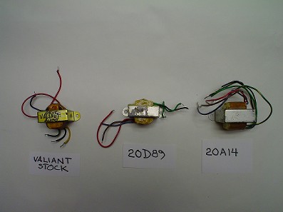
THE DRIVER
TRANSFORMER
The key element
to this whole modification is this sweet little driver transformer,
the 20A14, that is still available off the shelf. Most modifications
try to cope with the limitations of the original driver transformer.
I do not. Turns ratio is one to three step up, full primary to full
secondary. A Thordarson design, it does not exhibit the nasty 100 KHz
region peaks and resulting phase shifts the stock EFJ transformer
has. These high frequency peaks complicate stability in an inverse
feedback loop. In early hi-fi designs, knowledgeable engineers soon
distinguished themselves in the community by doing their homework on
the transformer design. No amount of inverse feedback can fully
correct the flaws of a crappy transformer. The 20A14 bolts up to the
same holes the original EFJ transformer uses! An insulator may be
required on the frame to keep it from shorting out the terminal
strips below it on the chassis. You will have to excuse me while I
rave about the beautiful specs of this transformer. The primary is
better than 20 Henries. The secondary is an astonishing more than 200
Henries! (The stock EFJ driver transformer is only 1 Henry on the
primary and just under 10 Henries on the secondary.) Wow!!!!! No
wonder the low end response of the 20A14 is so fantastic! When you
get done with your modifications, run a 500 Hz square wave from the
line input and you will see what I mean.
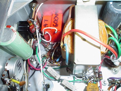
click on thumbnail to enlarge.
OK sorry, I
wore the markings off the exclamation point on my keyboard. I did
compare (and reject) an alternative 20D89 transformer, also available
off the shelf. It measured 1 Henry on the primary and about 11
Henries on the secondary. I considered it briefly because it is push
pull plates to push pull grids. It fell far short of the 20A14. The
iron is almost exactly the size of the EFJ stock transformer, so the
inductances are about the same. There is little cost difference
between the 20A14 and the inferior 20D89. Notice how much bigger the
20A14 is. It is sort of like being too rich or too thin. You never
can move enough air through an RF amp or have too much iron in your
transformer.
click on thumbnail to enlarge.
Also, the
secondary of the 20A14 is two separate windings. You might be curious
about this. Old Buzzardly designs in the 1950s handbooks allowed a
complex inverse feedback loop inside the power stage by feeding
energy from one tube plate to the opposite tube grid with a resistor
from the transformer return side to ground or bias. This
configuration resembles the neutralization of an old school plug in
coil push pull triode RF amplifier. This would be a dynamite way to
reduce the distortion generated in the modulator power stage, except
for one thing. Due to the resistance in the grid return, and the need
for grid current for class AB2, it won't work right. Bummer. However,
if you cannot find any more 2A3's to drive your 811s, you CAN use
this scheme with a pair of pentode connected class AB1 6L6s and this
20A14 transformer and get the low output impedance drive for the
811s! More to come........
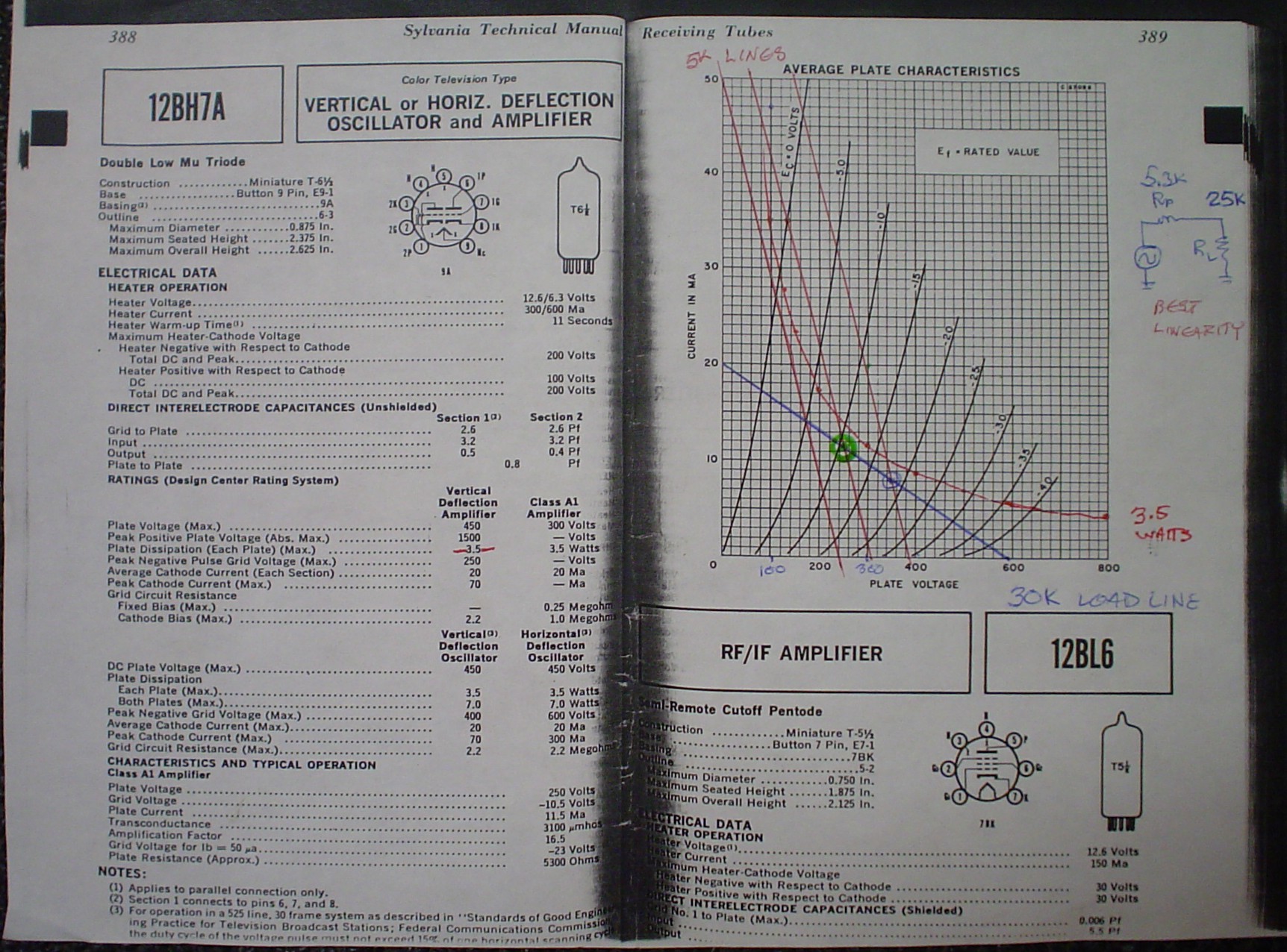
Some people
recommend using the 20A14 driver replacement transformer I have as a
step DOWN. This looks good on the surface to obtain a lower drive
impedance for the modulator grids for AB2. If you look at the load
line drawing on the tube characteristic curves I made, it shows that
the 12BH7 is out of limit on plate dissipation and nonlinear. Hooked
up as a step UP, it works correctly. I used feedback around the audio
system from the output of the driver to grids and sent it back
earlier in the audio chain just after the Low Pass Filter. This
results in the desired low impedance in the driver, which is
essential to achieving class AB2 which draws grid current in the
6146B. Again, a magic incantation I learned from an ancient wizard:
“Inverse feedback reduces gain, noise, distortion and OUTPUT
IMPEDANCE and raises input impedance.” Grid current can
be drawn without excessive distortion from the driver stage with the
inverse feedback the way I did it. Due to the low impedance of my
design, I only needed 270K swamping resistance across the secondary
of the driver transformer. Tim uses a lower resistance to load the
stock driver transformer to tame some of the nasty supersonic peak
and swamp out the load variations of the grid current. This
replacement transformer is only $25 and is commonly available from
multiple distributors. This also allows a push pull stage,
eliminating second harmonic energy from the driver distortion. The
driver stage is the ONLY stage that uses a cathode bypass capacitor.
The low frequency response using a 1000 uF capacitor across 2K is
sufficient to pass even low frequency energy from severe over
adjustment of the clipper stage without canting of the waveform.
click on thumbnail to enlarge.
I wanted to
maintain the clipper function. You may debate the wisdom of this, as
I discuss later. It is essential to retain the excellent low
frequency response provided by this 20A14 transformer to prevent
canting of the low frequency square waves coming out of the clipper
if you wish to enjoy the full benefit of its operation. When using
low level speech clipping, it is essential to reduce excess low
frequency response in the stages preceding the clipper and get the
stages following the clipper as close to DC coupled as possible. This
criterion is generally NOT observed in transmitters of this era such
as the Apache. The Apache uses coupling capacitors and a driver
transformer which are inadequate to use the clipper properly, causing
its “scratchy Apache” sound. The clipper, which is an
exact copy of a circuit in Terman Radio Engineer's Handbook, is not
the cause of the problems at all. Heathkit's defective implementation
is the true culprit. When using the line input with outboard audio
chains, you will appreciate the 20A14, which CAN drive the 6146Bs
into full class AB2 and still have good frequency response without
running 1000V on the plates of the 6146 modulators.
Here is the
stock audio before modifications.

click on thumbnails to enlarge.
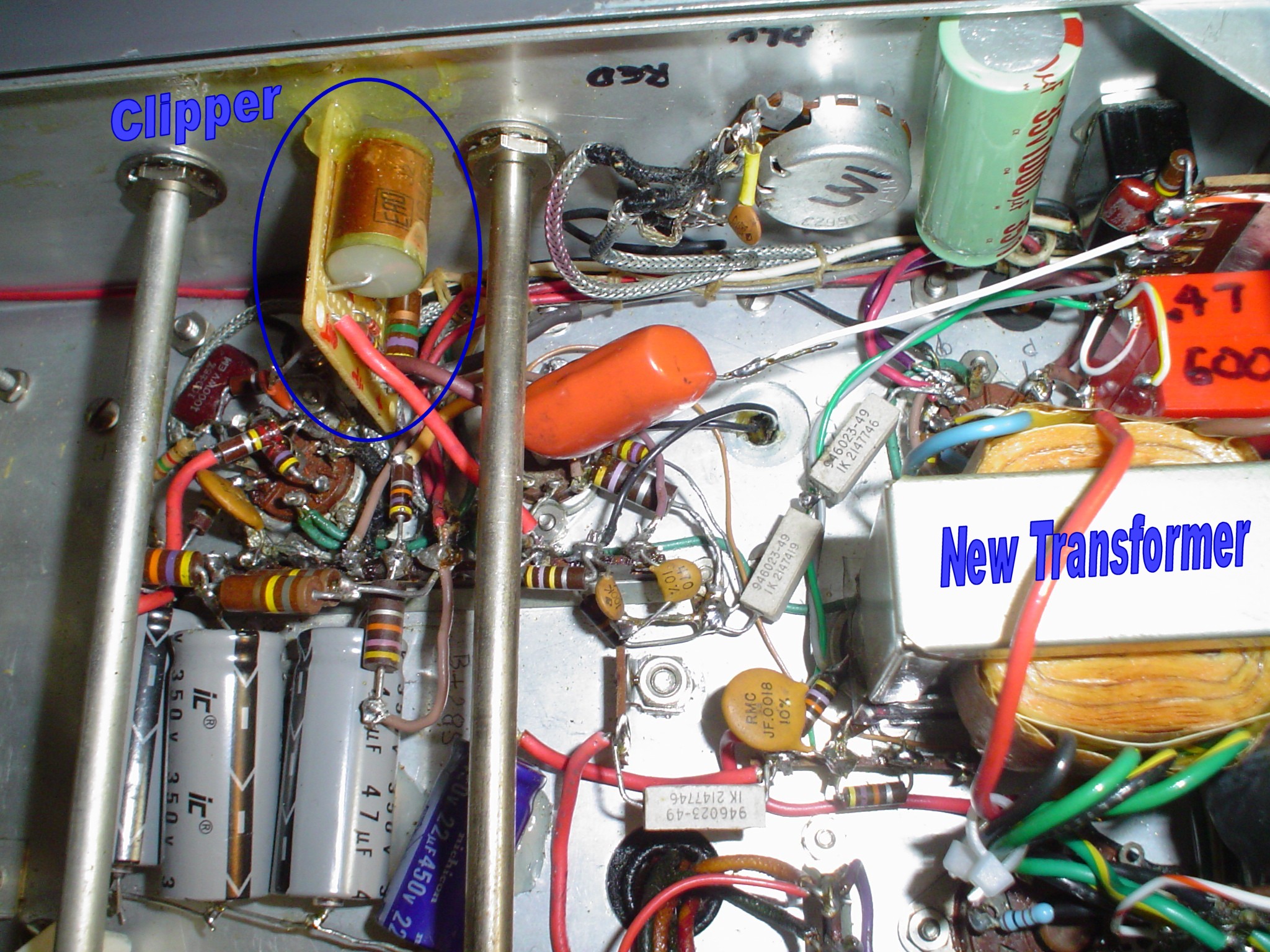
Here is the
completed work with the small added clipper board.

click on thumbnails to enlarge.
Many people
remove the clipper from their rig. They lose the over modulation
protection afforded by the limiter. It is better to make the limiter
work right. My design does that. The limiter (clipper) is solid state
diodes on a small circuit board. This frees the socket used for the
6AL5 for a 6AV6 amplifier tube for impedance matching and gain and
circuit design flexibility. I found that increasing the resistance of
the pot and another resistor noticeably improved the waveform in the
limiter. While the Johnson values are the same as common handbook
circuits, I found my mine seemed to work better. Driving it hard
makes clean looking square waves. The original circuit looks terrible
and depends on later filtering to reduce that. W8JI leaves the
clipper in and recommends shorting one of the diodes with a capacitor
if you want to only limit the negative peaks and allow upward
modulation to 130%. How he achieves this upward modulation percentage
without work on the output stage to make it work in AB2 or gets low
distortion output escapes me. I felt that 3 to 6 dB of gain
compression would provide better average modulation level punch than
the asymmetrical modulation, which vintage receivers do not tolerate
well. Synchronous detection will love the upward peaks. Everyone has
their own solution; just because they differ does not mean that one
or more of the approaches is wrong. I present my reasoning here, and
the alternatives to my approach; you are free to explore options. In
practice, no one seems to complain about smaller levels of clipping.
It just prevents splatter. Once you exceed 10 dB, people do not like
the sound for casual local ragchewing, but it does help some in bad
conditions. 18 to 24 dB will likely get you a “military sound”
audio report, and the EFJ manual tells you that. Excessive use of
clipping or any nonlinear compression techniques causes
"intermodulation distortion", a gravelly sound. This
results from harmonics and mixing products between all the
fundamentals and harmonics contained in the original voice signal. I
am sure that you have heard over processed SSB stations, especially
trying for a contest mode signal. Even properly done, it gets the job
done, but not nice for rag chews. Exercise common sense and
moderation in all things. If you do not want to use the clipping
function, turn down the gain control, don't hack it out.
Refer to
my article on splatter.
For more
authoritative information on frequency range for voice communication
and optimum clipping levels, consult the Radiotron Designer's
Handbook. It is out of print, but you can find a copy for about $30.
It is definitely a good resource.
AUDIO BANDWIDTH CONSIDERATIONS
If you want
more high frequency response, adjust the values of the modulator
secondary shunt capacitors as well as the small cap across the phase
inverter. My values were checked out by a local friend with a flex
radio and show an upper limit of 3.5 KHz “on the air”.
Vintage receivers like the HQ170 and 180 as well as the SX100 and 101
are not likely to hear much higher than that. You can tap into an
HQ170 or 180 at the 2nd IF of 455 KHz and get a hi-fi
signal under good conditions, but that is another story. Under
optimum conditions, with no band crowding, you can get away with
running a wider signal. One option is to put an “old school”
high level pi network LC splatter filter in a box mounted to the back
of the Valiant cabinet plugged into J8. A second standard plug with
only jumpers would be on hand to allow wider bandwidth. Use adequate
insulation and safety precautions. These are deadly voltages and may
contribute to arcing problems as I discuss in this article. I may
write this option up later, or get back to me if you have success
with it. You could also mount the capacitors used to “build
out” the mod transformer in the J8 mating plug, possibly with
multiple plugs available for quickly adjusting the high frequency
response of the system.
All other
stages in the audio chain have unbypassed cathode resistors. This
results in low distortion from each stage owing to the inverse
feedback from this configuration. Distortion in each 12AX7 stage can
exceed 2% without inverse feedback. Most designs I have seen employ
cathode bypass capacitors, which do not take advantage of this
improvement in the low level stages. This approach has lower
distortion and noise resulting from the inverse feedback. A magic
incantation I learned from an ancient wizard: “Inverse
feedback, reduces gain, noise, distortion and output impedance and
raises input impedance.” Use the 12AX7 as I show with no
cathode bypass capacitors. It has more than enough gain with a good
microphone.
If you want
more lows from the preamp, increase the two coupling caps from 0.002
uF to 0.0033 or 0.005 or even 0.01 uF for the second stage cap.
Keeping the first stage capacitor smaller and the second stage
capacitor adjusting larger adds some warmth lows but still retains
some presence rise that helps brighten the audio and increase
intelligibility. Remember, if you employ the clipper, it will sound
muddy if you run a lot of low frequencies through it. The values
shown worked OK for my voice and my Dee Ten Four mike, without hum in
the output. The important tradeoff is that if you run excessive low
frequency energy through the clipper circuit and crank it, the
intermodulation distortion increases and destroys intelligibility and
sounds gravelly. Do not exceed 10 dB of clipping ever. If you really
want wider bandwidth, you should use the line input anyway. I have
both available and adapt my use to prevailing band conditions.
Many recommend
a 10 Meg resistor in the mike circuit. I found that hum was excessive
in my rig with a D104 and higher values, so I stuck with a 3.3 Meg
and smaller coupling capacitors, especially in the input stage.
Encasing the resistor in shielding is said to help. Use shrink sleeve
to cover the resistor and cover it with grounded braid. I do not have
a deep voice, so I did not need to have extreme low end performance
in my solution. Experiment with the two 0.002 uF coupling capacitors
in the 12AX7 stage to add lows. The mike wire passes by the filter
choke and transformer, and is in a harness bundled with AC wiring.
Possibly using DC filaments in the audio section would help, but I
did not try it. I considered removing the MAN – PTT switch and
placing the mike connector there at one point. This rig had a custom
paint job. It made no sense to compromise its appearance. I have made
no changes above chassis that detract from its appearance.
The best way to avoid this entire problem is to use the W8JI D104 FET mod to drive the Valiant with a low impedance, which eliminates hum and frequency loss. http://www.w8ji.com/d104_to_low_impedance.htm
The driver
transformer will carry a lot of lows, but remember that the output
modulator iron is not designed for this and a lot of current flows in
the winding trying to produce those frequencies. When I had feedback
that contained the output modulator transformer, I noticed
frightening amounts of plate current trying to maintain a flat
frequency response for the lows. Keep this in mind if you use the
line input jack. It wants to see about 0.5 to 1 V of audio.
Extensive
square wave testing resulted in the values in the feedback network
and B+ decoupling capacitors.
OTHER REPAIRS AND
MODIFICATIONS
All the power
supply filters were beefed up. In addition, the Bias and Low B+
supplies were solid stated. Many people claim to reduce transformer
heating by just slapping a solid state diode in place of a high
vacuum rectifier. True, you save the filament current. However, you
get very high peak charging currents owing to not accounting for the
effective series resistance of the the tube diode. This causes excess
heating of the power transformer to the high peak currents. The DC
output voltages are all out of spec high. Often this damages the
marginal drive control pot and the Chernobyl Resistor in the VFO.
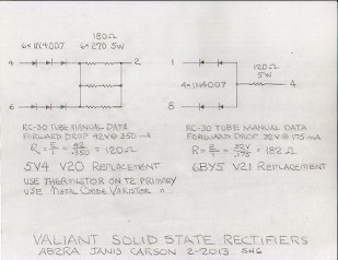
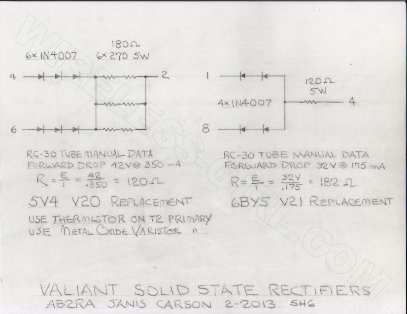
Avoid this. In the circuit diagrams, I provide the correct forward
drop as calculated from the RCA tube manual data. Examine the process
as explained there and you can create your own solid state
replacements for high vacuum rectifier tubes of any type, the right
way. Later, I may provide a separate file of vacuum tube rectifier
replacements as I develop them.
click on thumbnails to enlarge.
The green power
indicator is not very bright. I provide a #47 bulb replacement LED in
the schematic section. The average value of 0.318 times the peak
value comes from circuit theory and is used in common older VOM
circuits to calibrate their AC ranges when employing a half wave
rectifier for an analog meter. You can use this same technique, with
adjustment to the resistor value, in other applications. If you use
something other than the Radio Shack LED specified on the schematic,
you will be able to adjust the resistor for your part using the math
on the schematic. In addition, the Radio Shack 276-0024 LED has a 130
degree viewing angle and might work well to illuminate the VFO dial
if properly mounted; I did not try it yet. It also may find a home in
my HQ180. Look at the schematics and calculations and you will see
how to do it.
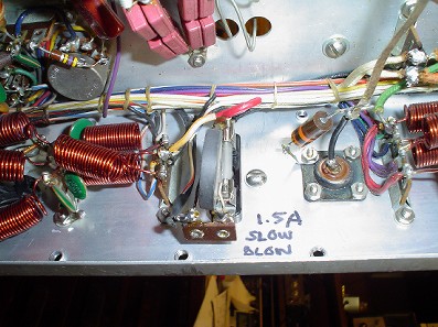
I also replaced
the internal Low Voltage and Filament Transformer fuse with a fuse
holder that is accessible from outside the cabinet. A tube saver
thermistor and a Metal Oxide Varistor (MOV) complete the AC line
improvements. This affords some protection from surges and start up
current. You can also use the 5 volt rectifier winding to reduce the
primary voltage to the low voltage transformer. The winding for the
866s is only 2.5 volts and not worth the trouble of stealing it.
Also, the commercial solid state replacements for the 866s behaved
very strangely without the filament voltage. I suspect they use the
filament winding with an scr type circuit to fire the rectifiers at
zero crossing. This seems to result in no "thump" when
the plate supply is first turned on. I did not pursue it further. Two
essential guidelines I operate by: "If it ain't broke, don't
fix it. If you tinker with something long enough, you will break it."
The whole high voltage section, including the 2.5 V filament winding
is something better left alone if possible. Use 3B28s to replace the
866s. They have very low forward drop and work great.
Click thumbnail to enlarge
I retained the
original fuse plug, but I run a hefty ground lead to the cabinet and
am aware of the risks. Putting a fuse in the neutral of the AC line
is not a good idea without a good ground on the rig. Finding a place
to mount the proper AC fuse for the rig is problematic. I may revisit
this in the future, if I can find a spot on the rear apron. In that
case, a three wire grounding plug is going to be installed. You can
mount the fuse holder where the SSB input is, but I use that for my
frequency counter.
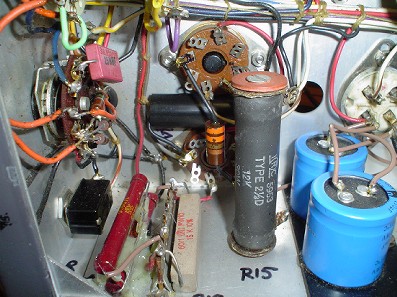
If you have not
done it, replace the Chernobyl Resistor in the VFO. This is the 18K
carbon resistor in the screen and regulator circuit, R3. I do not
recommend removing the VFO from the rig due to possible damage to the
unobtainium VFO shaft coupling. I have a pictorial tutorial showing
how to remove the side panel near the VR tubes and mount the new wire
wound resistor below the chassis on a terminal strip held by the VFO
mounting screws. Don't make it harder than it is. See my expanded
article on the VFO.
Click thumbnails to enlarge
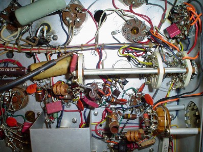
Before you reassemble the transmitter into the cabinet, there a three more VFO related items you must correct. This appies to the Valiant and the Ranger, or any other E. F. Johnson transmitter with an internal VFO.
First, you must properly ground the Plate Tuning capacitor for the final amplifier. The metal shaft for tuning passes right by the VFO. On 40 meters, all the RF stages operate on the output RF frequency, or as we call it, "straight through". This results in the VFO frequency changing or "pulling" from the frequency you set in zero beat mode at low power. The fix is very simple: replace the fiber washers between the Plate Tuning capacitor and the metal chasis with metal washers of the same thickness. This idea comes from W8JI.
https://www.w8ji.com/johnson_vfo_chirp_jump.htm
He shows in photos exactly how to do this. It is a very simple modification that you should do while you are in there. I left the buss wire in place and grounded the capacitor directly with the washers and it worked for me.
A second improvement you can do to get the "spot" frequency to match the transmit frequency is to put a jumper wire on the "spot" switch. This wire should key the exciter stages (with the Plate Power switch OFF). I do not have the schematic on how to do this, but if you trace the wiring, it is clear. The "spot" switch only keys the VFO as wired from the factory. You have to wire it so it keys the exciter stages as well, just as it would do it if you pressed a key plugged into the key jack.
This modification works by having the same load on the VFO as it would during transmit.
The third important fix is in the alignment of L17. You probably have to recalibrate the VFO, since you disturbed its wiring while replacing the Cherynobl resistor. You should also go through the rest of the alignment process. One source, I think WA2QIX, I cannot remember who, found that L17 should be unscrewed all the way up instead of peaked for maximum drive. Adjusting by this method cures the VFO FMing during modulation. If your signal is observed on an SDR or spectrum analyzer, it will have non symettrical side bands. That should not happen with proper AM. This simple L17 alignment tip will reduce FM or phase modulation, cleaning up your signal.
I have also heard from multiple correspondents that adjusting L17 all the way to the top also reduces chirp in the E. F. Johnson Valiant. Besides curing the FM on top of AM problem, this apparently is a proper fix for some sort of loading problem. Perhaps if the VFO were located outside the transmitter cabinet as it is in the Viking II, this problem might not be as severe.
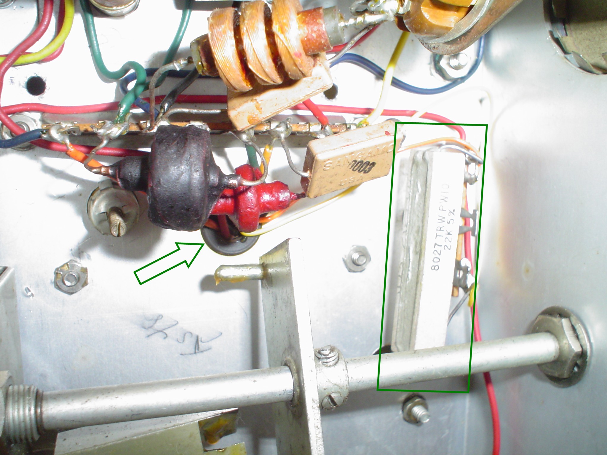
WA1HLR
recommends placing a 5K 5 to 10 Watt wire wound resistor in the LV B+
side of the drive control R51. I strongly recommend this along with
the rectifier design included in the schematics to avoid excessive
power supply voltage. He recommends another 5K in the ground return
side. I found that 160 Meter drive could not be reduced to spec with
this value. Maybe my tubes were newer and had more gain. Try a lower
value fixed resistor if that is your problem. My rig arrived blowing
fuses due to a bad drive pot shorting the B+ to ground. I did not
have a 25K pot in my junk box. I used a 20K pot with 22K in the B+
end and no resistor in the ground end, and it worked fine for me.
Drive was OK on 10 and 15 meters with this configuration. I super
glued the extra resistor to the back of the pot as shown in the
photos so it was not just flopping around trying to short out.
Timtron is correct in pointing out this chronic problem; I just had
to improvise with what I had in stock. If your drive pot has not yet
failed, do this before it does. As an exercise, do the math. The pot
is running at its full 4 Watt rating under ideal conditions in the
stock Valiant. With high line voltage or improperly done solid state
power supply, it gets worse.
Refer to this page: Drive Control.
Click thumbnail to enlarge
Removing a bad
drive pot or clipper control comes with its own problems. There is a
nut between the front panel and an L bracket mounting the control.
This allowed the rig to be operated without a front panel for
testing. To avoid removing the front panel and the extra labor and
risk (to the VFO drive), I use the following technique. Remove the
knob and front panel nut and washer. Remove the low level tubes from
the modulator near the control. Remove the wiring from the control.
If the control cannot be unscrewed from the back easily, grasp it
firmly with pliers (its bad anyway, so crushing it slightly won't
matter). Use a thin screwdriver to keep the captive nut turning as
you back the control out. Slide an old short pencil in the front of
the hole to keep the nut from falling down inside as you remove the
bad control. To keep the nut in place, insert the new control as you
withdraw the pencil. You can either allow the old nut to remain or
remove it and replace it with a flat washer. Something is needed as a
spacer to avoid dimpling the front panel when you tighten the front
nut as you reassemble the rig.
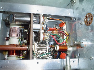
RF TANK CIRCUIT
MODIFICATIONS AND REPAIRS
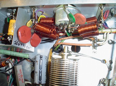
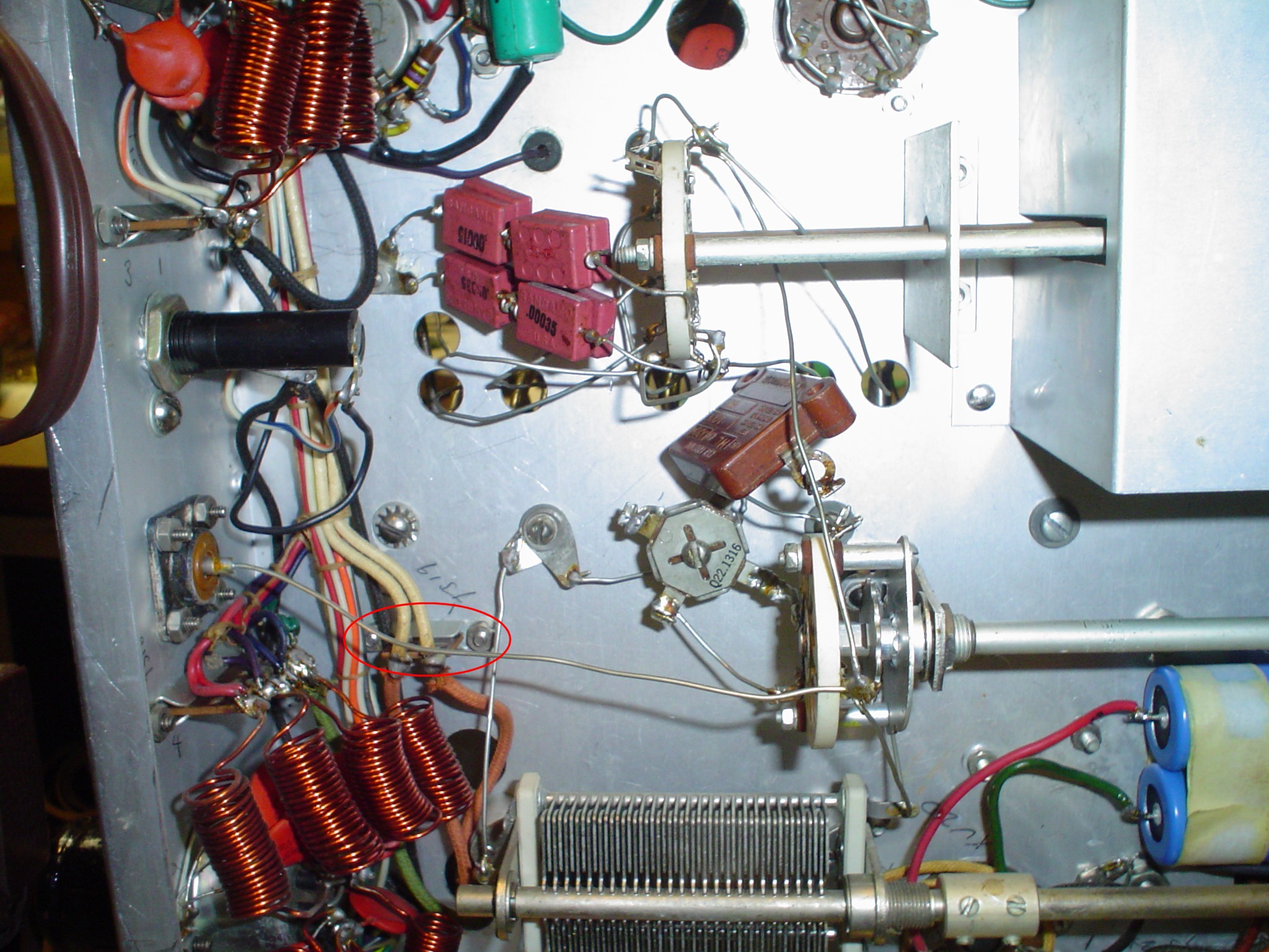
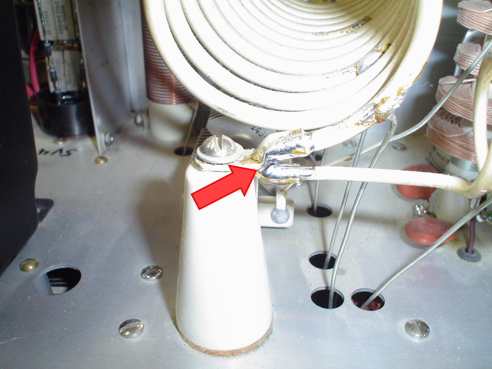
One important
thing that I do for the RF deck: SOLDER the connections in the plate
tank coils. The screws may loosen and all hell can break loose
intermittently if you do not. An excessive amount of solder is not
required. See the picture of what I did.
Click thumbnail to enlarge
The Valiant One schematic
shows a 2000 pF for C37 coupling the 6146s to the tank circuit. My
Valiant One had 500 pF. The Valiant 2 uses 500 pF. WA1HLR recommends
replacing the lower value with 1000 pF for better efficiency on 160
Meters. It does not seem to contribute to any condition which might
cause circuit failure if you leave it as is. If you do not use 160,
maybe you can leave it alone. My rig had screws mounting C37 that
would not budge, so rather than breaking something, I just let it be.
Maybe sometime I will solder in a 500 pF in parallel. Power output is
down about 10 – 15 watts on 160. This might help it.
On the other hand, EFJ does
not maintain the circuit Q properly on 160. This might account for
some of the power drop off. To do it right, the 160 coil L39 would be
reduced and another padder cap like C39abcd would have to be switched
in. After modification, would the tuning range of the existing
variable C8ab be enough to tune the whole 160 Meter band ? More
modifications to the band switch and coil winding was not justified
in my opinion at this point. Increasing circuit Q might improve
harmonic suppression and output. If you use the Valiant on 160 with a
high impedance or multiband antenna, be sure to use a tuned link or
"low pass" style antenna tuner. The common C-L-C
transmatches on the market are a HIGH pass, which afford no harmonic
suppression.
The Valiant is in no way
inferior to any other rig of its time. The Viking One and 2, DX100,
and others all just throw a padder coil in to get on 160 without
proper attention to circuit Q. (I put an Apache on 160 with the
correct circuit Q and the addition of a 100uH coil in series with the
stock grid driver coils. The Apache VFO operates on 160 and 40 and
multiplies into the other bands exactly like the DX100. Incidentally,
standard 6146s in class AB1 might be a good substitute for the 6CA7s
in the modulator. The 6146 plate impedances might "bolt up"
just fine to the stock Apache mod transformer. The 6CA7 is way
outside its specs on plate voltage in the Apache, and the screen pin
arcs to the plate pin on the socket and tube base as happens commonly
in guitar amps. I may write all this up some day in a separate
article.) None of these rigs seemed to result in OO reports when
using a coax fed low impedance antenna with good SWR. Direct feed
(without a tuner) of a high impedance or high SWR antenna will likely
be risky, in my opinion, regardless of EFJ claims to matching 600
ohms direct from the radio.
I also put a
30K 2W resistor across the RF output terminal. If you use an antenna
or tuner that does not provide a DC return, voltage can build up and
destroy the output fixed mica capacitors or coarse loading switch
contacts. Normally, a 2.5 mH RF choke is used in later designs after
they discovered this problem which also afflicts the Viking One and
Two, DX100 and Apache as well as other rigs. Self resonances can
occur in RF chokes, so I just threw a resistor in to solve the
problem without going into extensive testing with a grid dip meter
and so on. NEVER change the settings of the band switch or coarse
coupling switch at full power. Load the rig in CW mode, let up on the
key, change the coarse loading, then key up and complete the
adjustment using the FINE loading only. Do not just fire up in AM and
let the plate meters (including the modulator) fly where they wish as
you madly tweak everything. Sooner or later, something unobtainium
will fry.
CONNECTOR ANNOYANCES
There are two
connector annoyances that Johnson inflicts on us. First is the @#%
antenna relay connector. Buy a good quality two wire extension cord
to be cut in half. I put the socket end of an extension cord outside
the rig and pass the wire through the AC cord grommet. Solder the
wires to the "crystal socket" terminals INSIDE THE RADIO.
I use the remaining plug end of the extension cord from the first
step to wire the antenna relay coil. Solved.
Second is the
mike connector. The LV B+ is used on the PTT circuit. If you plug a
mike in with the power on, the two connections can make before the
ground connection. This passes DC through the mike element,
destroying it instantly. Fortunately, my grandfather worked for the
Erie Railroad and could go a half hour with profanity and never
repeat himself, and I have learned that method of stress relief for
this sort of occasion. I use a 4 pin standard mike connector that
Radio Shack stocks. This provides a good connection for the ground
lead. Use BOTH of the extra pins for ground if you are paranoid, but
this will make the mike incompatible with other rigs.
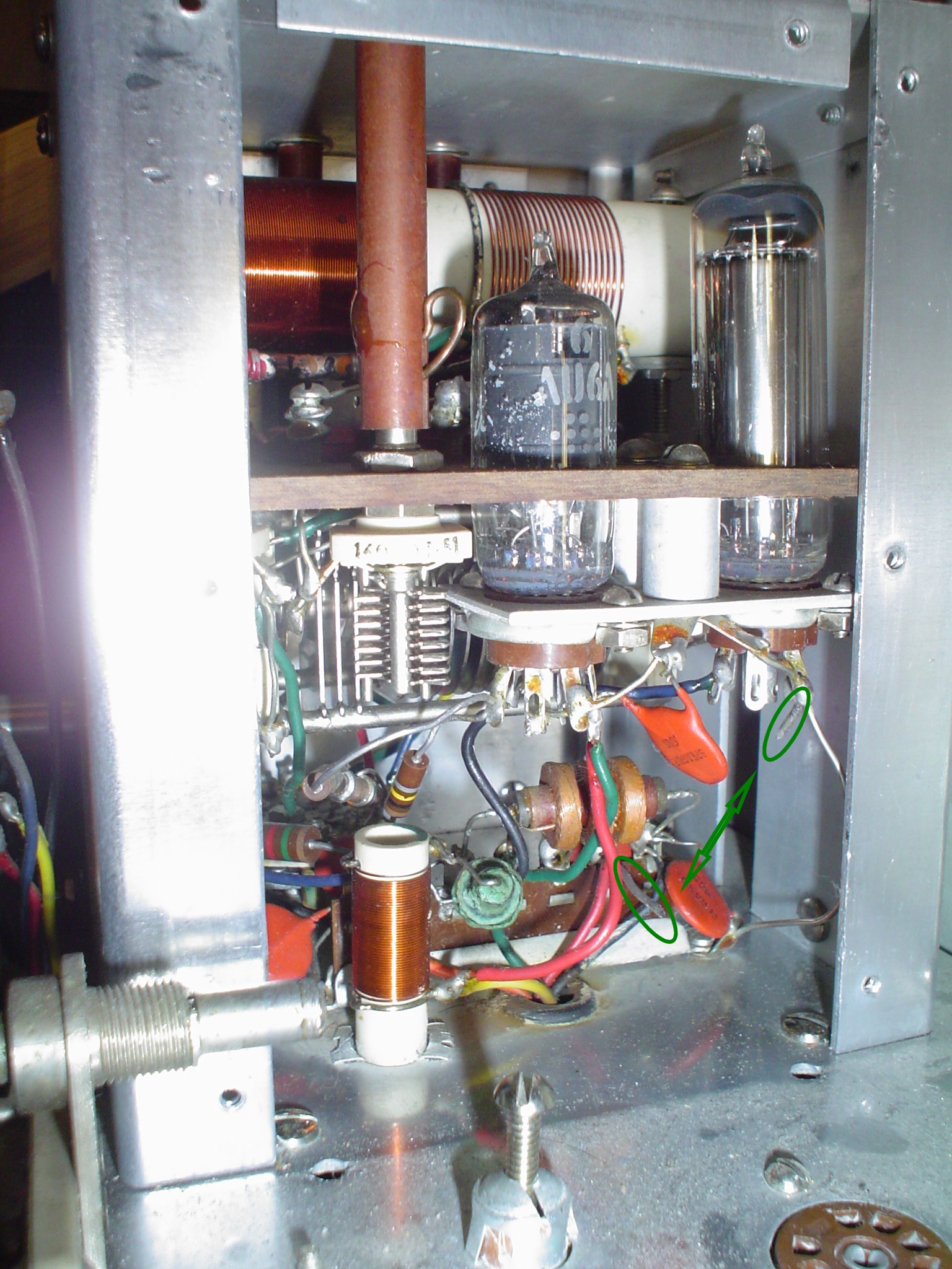
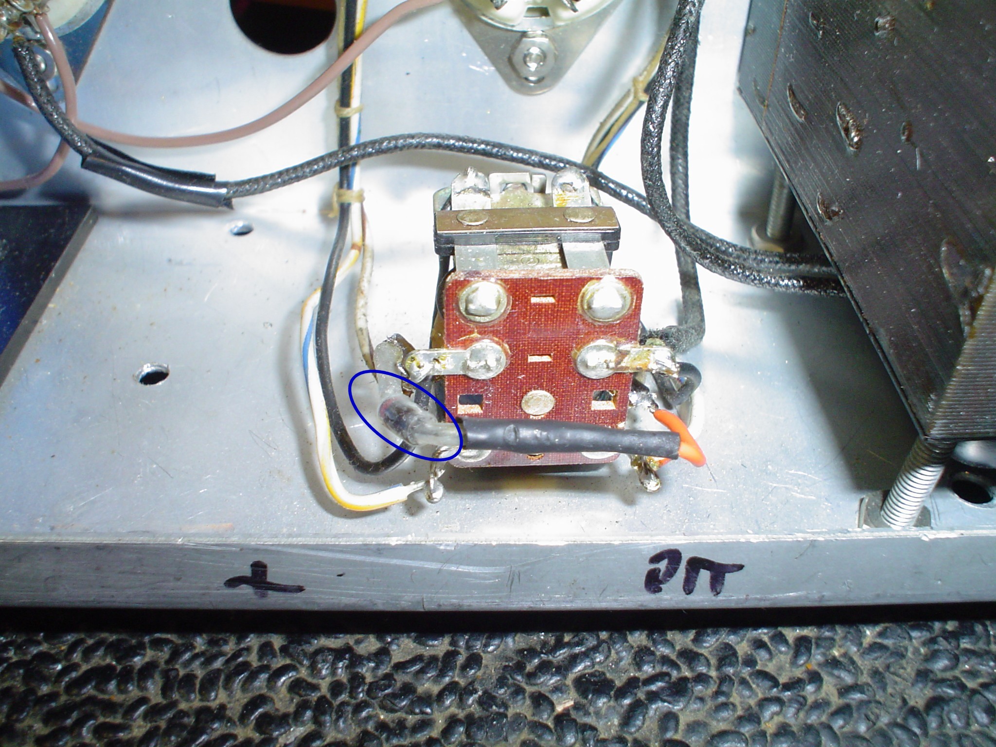
I also put a
"catch diode" to suppress the spikes generated by the
coil of the relay. The diode connects to the COIL of the relay, not
any of the contacts or AC or keying circuitry. This diode only
conducts briefly when you unkey the radio to "eat" the
inductive field collapse. The BANDED end (cathode) points to the +
supply side. The anode goes to the PTT side of the coil, which is
grounded by the plate switch or the mike PTT line. Use a meter to
double check the wiring in your radio matches mine. This is not
completely necessary, but reduces sparking on the mike's PTT
contacts. It would be better to rectify some of the filament supply
and use a low voltage relay.
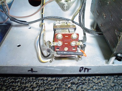
Click thumbnail to enlarge
OTHER ITEMS YOU MAY
WANT TO ADDRESS
A low voltage
relay, or better yet, a solid state relay for the plate transformer
primary and a transistor to drive the exciter keying would be even
better. If you do this, be sure to retain the safety links in the VR
tube sockets to prevent activation of the HV B+ with the VR tubes
unplugged or you may regret it. Your will to modify and parts supply
will govern whether you want to pursue this.
The keying line
is in excess of 200 volts can bite you or destroy your keyer.
Adapting the circuit to be more like the common Johnson modification
to the Ranger, which has lower keying voltage, might be a good idea.
Alternatively, a high voltage transistor to isolate the key jack
might be another approach. The later keyer in the Ranger used lower
bias voltage. You can reverse connect a 12 Volt filament transformer
from Radio Shack or your junk box to get the lower bias voltage for
the keyer.
I also put a
wire jumper on SW4A mode switch. This allows the morse key on the rig
to key the exciter stages in all modes. You now can spot with your
crystals or the VFO. It allows me to use my frequency counter without
putting a signal on the air. It saves wear and tear on the
VFO-crystal switch or AM-CW-SSB switch just to get on frequency. If
there is any jumper on the J2 Key socket to short the connector when
no key is plugged in, remove it or the circuit will always be closed.
I set a large
muffin fan above the finals to cool the cabinet. Some cushioning
prevents cabinet scratches. Not as effective as cutting a 4 inch hole
in the back, but it does not damage the unit as a collectible. I also
put some small pieces of wood under the feet to raise the cabinet for
more airflow into the bottom chassis. Long "Old Buzzard"
transmissions still leave things nice and cool.
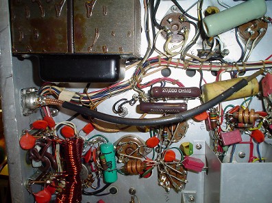
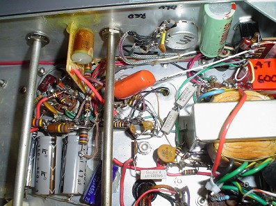
One of the high
wattage 12K resistors is just flopping on its leads. Normally this
hangs off one of the unused tube socket pins of the 866 rectifier.
Mount it to the chassis, but use insulating washers. Or add a
terminal strip.
Click thumbnail to enlarge
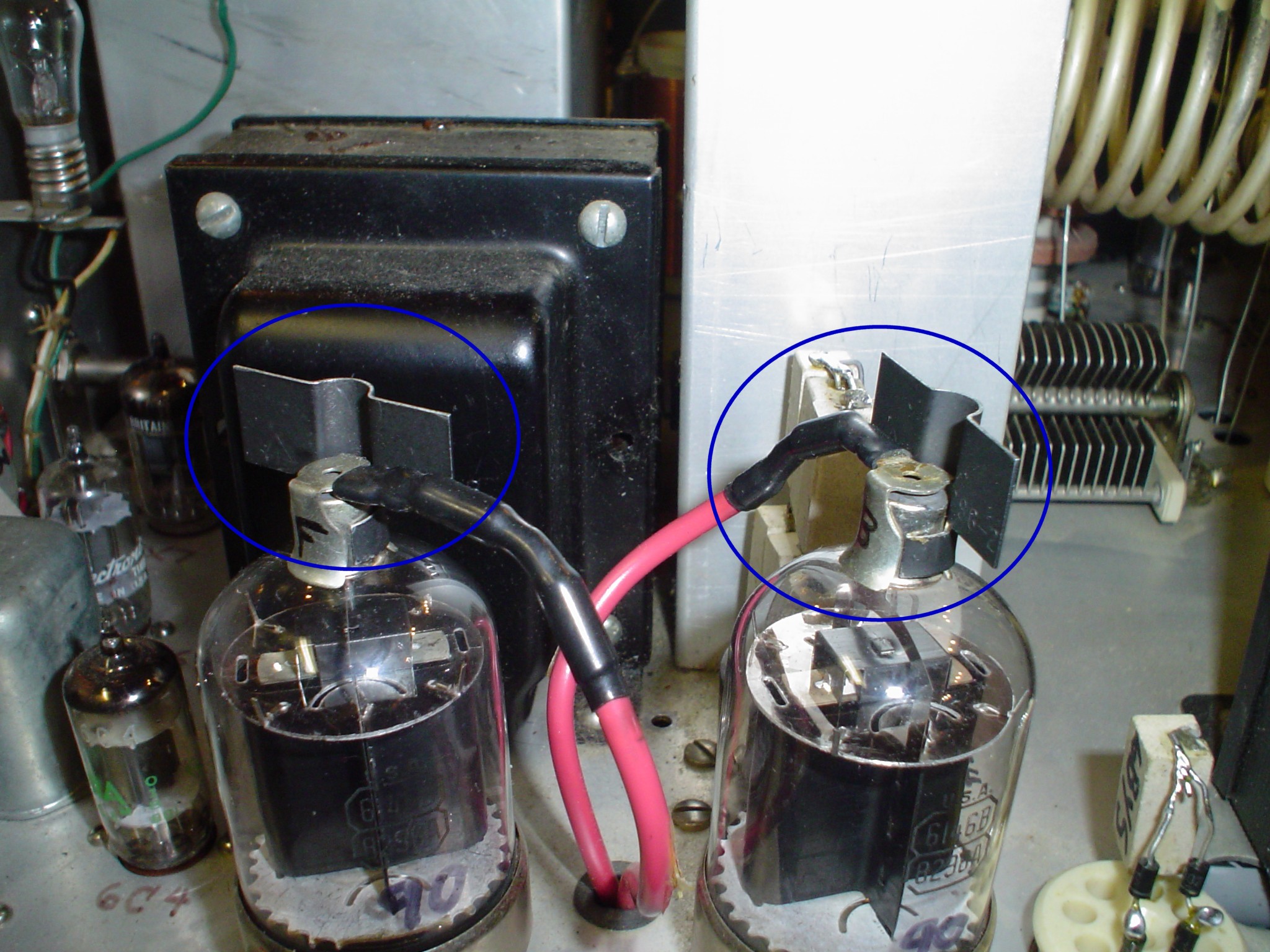
Heat sink plate
caps help, see the pics. These are designed for transistors, but they
seem to work well on the tubes too. The larger commercial plate caps
of massive aluminum are nice, but they should be painted black for
best dissipation. Also, the crowding around the RF choke and copper
strap makes them difficult to fit. Even these small heat sinks make
the plate seal noticeably cooler after a long transmission.
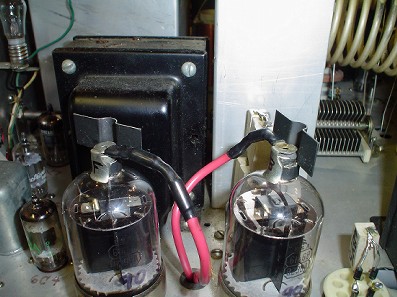
Click thumbnail to enlarge
At the expense
of being concise, I included some thoughts on ideas that I discarded.
This is to save you the frustration of trying them out and finding
out they do not work, the same as I did.
Everyone has
their own solution; just because they differ does not mean that one
or more of the approaches is wrong. I appreciate them taking the time
to put their ideas out there to help others. They risk someone
disparaging their work when they do, but do it anyway. I present my
reasoning here, and the alternatives to my approach; you are free to
explore options. By explaining my methods, even if you do not do any
modifications, it may provide some ideas to begin your own work. I
hope you found something useful.
RECOMMENDED
READING:
- The Radio Handbook 15th Edition especially pages 300 and 301 on clippers and filters
- The Radiotron Designer's Handbook 4th Edition
- The Radio Amateur's Handbook 1954 Chapters 9 & 10
- WA1HLR's article on improving the Valiant
- W8JI's articles on Johnson transmitters
UPDATE 1-10-2014: W1CKI full audio chain distortion reduction feed back circuit
I have just run across the best inverse feedback circuit I have seen on the
web. It is a similar design to mine, uses the exact same driver
transformer, and tubes. I plan to implement a version of it to get even
better performance in the driver section as soon as I get a backup AM rig
running (Viking 2).
UPDATE 2-5-2014
I have been researching the "next step" feedback and found something at Electric Radio which has me rethinking the whole process. I am referring to Electric Radio #203 and #204, the April and May 2006 issues of Electric Radio magazine. You can obtain copies of back issues at http://www.ermag.com/.
This modification is by far the best I have seen. I wish I had seen it before I began this process. It would have changed the outcome. I am not disappointed with what I have now, and probably will just go ahead with the W1CKI component values for the inverse feedback addition to my mods. I am getting good reports now.
The mods articles are written by well known vintage transmitter expert Chuck Felton KD0ZS.
If you have not yet begun any work on your Valiant, I strongly encourage you to give his work a look before you even take the screws out of the cabinet.
Here are its features:
- Transformerless grid driver circuit. About the stock Valiant driver transformer, Chuck Felton states: "It is the worst thing you could have after a clipper; it's trash." You gotta love a man who calls it the way it is. However, it does not suffer the power limitations of the "East Coast" mods, since it is a low impedance driver. The 12BH7 driver for the 6146Bs is a cathode follower circuit.
- The clipper is retained for a modulation limiter to keep peaks from exceeding 100% negative.
- It can be configured so that the positive peaks can exceed 100%, using W8JI's suggestion of bypassing one diode with a capacitor.
- An overmodulation peak indicator is included in the design to allow adjustment of levels without having to have your scope on all the time. This will flash when you hit the baseline, telling you to back off just a tad.
- DC coupling is employed in some amplifier stages. Elimination of coupling capacitors extends low frequency response to zero Hz.
- A clever linear compressor keeps talk power up.
- Negative Feedback is applied around the modulation transformer, reducing distortion and improving bandwidth.
Basic improvements to the Valiant include:
- Bias circuit adjustment pot mods for better range of adjustment.
- T/R relay improvements
- Improved VFO stability on higher bands
- Front Panel mike jack, which is something I considered to reduce hum.
- A fix to prevent failure of the fixed loading capacitors.
UPDATE 11-25-2015
On 2015-11-24, "John" wrote:
Hi Janis:
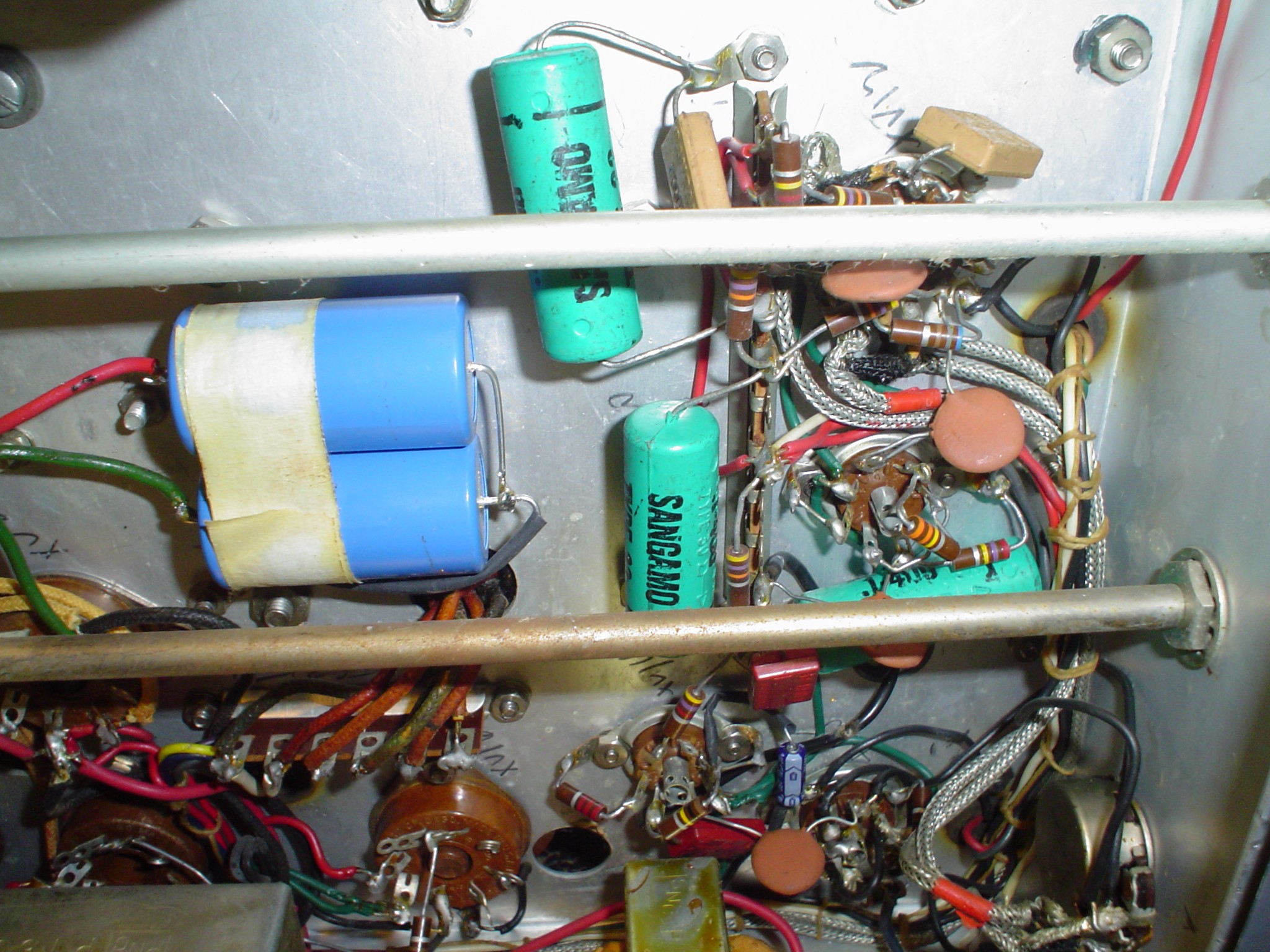
A friend of mine just got a Valiant that is in very good physical condition so being a fanatic he has decided to replace all the caps. I think I have talked him out of replacing the square mica caps, and certainly he should replace any high voltage electrolytics, but I wonder about the green Sangamo caps..??? I noticed in photos of Valiant restoration you posted on the internet that you show those caps. Another question is whether to replace the 866's with 3B28's?? I recommended for him to do that, but what is your thought on that..???
Thanks
My response:
People go nuts replacing good parts in a shotgun rebuild. Often they do not run the rig to see if it is repairable first and they introduce new problems in addition to the existing ones. You can fall into the fallacy: "If it ain't broke, fix it till it is."
I do recommend replacing the electrolytics with units from Hayseed Hamfest (not sure of the name) but he tries to get original appearance. Otherwise, use 105 degree Centigrade units for better heat failure performance instead of ordinary 85 degree C.
Also, 3B28 for 866 is a good idea. Or use the solid state ones from K2AW silicon alley. One problem can be the arcing from the filament winding of the LV transformer that runs the 866s. 866s will flash back if the room is too cold and you have not warmed them up long enough, and this can aggravate the arcing till a carbon track develops. Getting rid of the 866s is a very sound idea. Good luck finding a place to dispose of Mercury. (Warning: DO NOT BREAK 866S AND TOUCH OR INHALE THE MERCURY FUMES!!!!) See the arc pics on my webpage. If you go totally solid state, that filament winding and all the crappy terminal strips can be disconnected from the HV circuitry and it never becomes a problem. The 866 is low forward drop device, so solid state is OK with maybe a 50 ohm wirewound in series with the filter choke to act as a fuse if something shorts. Use the method shown for the 5V4 in the schematics to choose the value. I have always just plugged in 3B28s as a direct no mod sub.
The square mica caps in the loading circuit can fail, but I generally find they fail due to moving the coarse loading selector switch during full carrier tune up in AM mode. NEVER TUNE UP IN AM MODE. Use CW mode, and unkey the carrier, THEN move the coarse coupling switch to avoid damage to the switch and mica caps. The fine coupling condenser CAN be moved for touchup of plate current in AM or at full carrier. Its the same thing as changing the bandswitch on your linear while transmitting at full power. Or switching the inductor switch on your transmatch while transmitting.
The other failure mode the loading fixed mica caps have is too much voltage from static pick up on the antenna, or modulation peaks coupling thru the plate blocking condensers on the RF final. Note this is not a problem if you use a Johnson Transmatch, because it has a coupling link which effectively shorts out any DC. If you put a 2.5 mH RF choke across the antenna connector, it bleeds off that DC voltage, which when added to the modulation peaks, can exceed the voltage rating of the mica caps. A 33K 2 Watt NONINDUCTIVE CARBON resistor works just as well and does not have the risk of RF resonances. One of the commonly sold newer (Hammond) 2.5 mH chokes has a ferrite core with some nasty resonances.
These loading caps can fail if you try to load directly into a highly reactive antenna like the G5RV, since the RF circulating current is too high. I would never run mine into over a 5:1 SWR, which is why I show the broadband dipole on my webpage. The Valiant has limited tuning range on 75 and 160, and the plate tuning will not give a correct dip all the way across the band, especially if you use CW also. My valiant was quite happy with the bowtie dipole.
Mica caps CAN fail due to moisture getting in from older style potting methods. New dipped micas are not subject to this failure. You can do a leakage test on them if you have a condenser checker. If they work and show acceptable leakage, I would not bother changing them. The older WW2 surplus caps like in the HQ129 should maybe be changed in B+ circuits, but the ones used in the Valiant are better and more reliable.
By the way, if you need band switches or a coarse coupling switch, you can get suitable ones from Ameritron. Or the wafers from Harbach electronics used in the SB200 are good.
On audio mods, I now recommend using W8JI method and possibly the P-T156 or Hammond 124B driver transformer; but changing the final screen resistor and grid leak resistor as Timtron and I describe will improve RF linearity and reduce distortion and are minimal work to install.
| 


