|
I get a lot of email requesting information on mods by the Timtron. They are by far the best "low impact level one" mods out there, and address the audio problems as well as the common reliability problems. I will show the relevant photos and schematic here, to tease that out of my article. For more information, I recommend that you read carefully the whole article, both of them. But I am providing this as a digest of my page specifically on how I installed Tim's excellent work.
WA1HLR articles:
http://www.amwindow.org/tech/htm/valiantbytron.htm.
Tim works with the original transformer. I believe that $50 for the new Hammond 124B transformer does more than any other expenditure to improve the Valiant. There is a new transformer for only $16 that I have evaluated and it is fully specified including DC current. It works well in my Viking II. That alternative transformer is the P-T156, available from a number of distributors. It is an exact replacement for the Stancor A-53C.
https://www.tubesandmore.com/products/transformer-audio-interstage-10-ma
But be sure to do the stuff for improving reliability, like the DRIVE POT modifications.
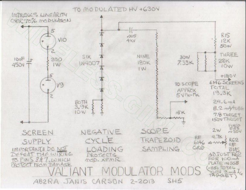
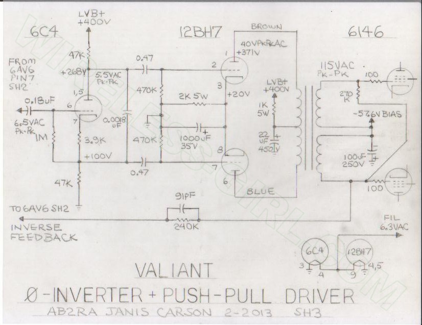
MY SCHEMATIC, WHICH SHOWS EXACTLY HOW TO DO THE WA1HLR MOD WIRING, THE VALUE OF THE RF AMP SCREEN RESISTOR, THE NEGATIVE CYCLE LOADING AND ALL THE GOOD STUFF: (click to enlarge)
This schematic is applicable to either PUSH PULL or SINGLE ENDED DRIVER. Both W8JI and WA1HLR recommend increasing the value of the RF final screen resistor. So do I, because it improves linearity of the modulation. This is the big one on top of the chassis, not the small one of the same value under the chassis which drives the VR tubes.
I recommend that you install negative cycle loading, which is a diode string (for enough voltage rating) and a load resistor for the modulation transformer in the event the audio is trying to drive the RF final plates negative. This is important to protect the modulation transformer. DO NOT insert a diode in series with the RF amp end of the mod transformer to try to disconnect the modulation transformer on negative cycles. This is a technique that was abandoned in the mid 50s and shows up in handbooks of that era. Newer handbooks do not show that. Do not remove all capacitors from the rear 9 pin connector or the final compartment RF bypasses to ground near the big RF choke. These provide some load to the modulation transformer, and prevent splatter. Do you really want a signal 8 KHz audio or 16 KHz RF bandwidth when you operate on 7295?
For a "level one" repair and mod, this is really all you have to do to increase reliability and frequency response and reduce distortion. If I had it to do over, I probably would have taken a tack more like W8JI and WA1HLR. I read the specs on the various flavors of 6146s and went that way in my design, and it is a lot of work.
I explain in my article why the "East Coast" style mods with a tricky little phase inverter does not provide full modulation due to no class AB2 in the audio final. W8JI comments agree with me. But read them for yourself, if you want to see what it is. I am not afraid to dig into the rig and improve it; but taking apart the mod transformer is not the kind of chance I want to take, given the difficulty of finding a replacement if I mess it up.
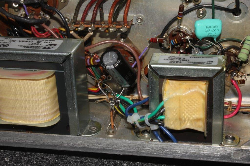
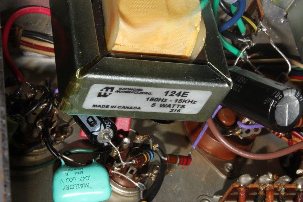
OOPS! What if you bought the 124E instead of the 124B or P-T156 and now want to use that in single ended stock Valiant mode instead? I get inquiries on this, and have "teased out" the Timtron mods on this separate article. MY modifications include much of Tim's work, but it may be hard for people to separate them. This page is to explain ONLY TIM'S mods.
Thanks to Philip, KA4KOE, who shares this with us, and it works.
If you want to use the 124E as a STEP UP transformer with a single ended driver stage (stock valiant, minimum mods), use these connections:
- SECONDARY:
- BLACK AND GREEN-YELLOW GO TO NEGATIVE BIAS.
- BLACK-YELLOW GOES TO ONE 6146 GRID.
- GREEN GOES TO THE OTHER 6146 GRID.
- PRIMARY:
- BROWN TO LOW VOLTAGE 300VDC B+
- RED TO 12AU7 PLATES IN PARALLEL (NOT PUSH PULL)
- BLUE NOT CONNECTED, INSULATE
NOTE: If you want a less radical step up, try the 12AU7 plates to the blue wire and leave the red wire disconnected. I have not tried this, but it may give results that please you better. Remember, this transformer is built for a balanced current from the brown and blue leads, which gives net zero flux in the primary at the quiescent no signal condition. Using the entire primary may get you too close to core saturation and affect the frequency response. I still recommend the 124B or P-T156 for single ended stock Valiant driver configuration, and offer this alternative if you have the 124E on hand.
NOTE: (Updated 12/23/2014)
The Thordarson 20A14 used in this article is no longer available.
I have received a number of inquiries about the interstage transformer used in this and some of the other mods.
This update provides all the information needed to select and procure the right transformer
for all styles of modifications.
Hammond makes an exact replacement the 124E. The specs are identical to those on the data sheet in this article.
You can read them at: http://www.hammondmfg.com/pdf/124E.pdf.
You can buy this transformer from the following places:
ADDITIONAL NOTE: If you want to do any of the mods like the W8JI or the TimTron mods and keep the single-ended stock 12AU7 paralleled cinfiguration, consider the Hammond 124B or P-T156.
The 124A is more like the original Valiant or other Johnson rig driver interstage,
but for the small increase in price, buy the 124B or P-T156 and get better than original performance.
If your Ranger, Viking II, Valiant, or other Johnson Transmitter burns out an audio interstage transformer,
this is the replacement that works perfect and fits the original bolt hole pattern.
It also would be perfect for a DX100 or Heathkit Apache.
This is a true high fidelity transformer. Read the specs at:
http://www.hammondmfg.com/124.htm.
Here are links to the photos and schematic for the E. F. Johnson Valiant Modifications by WA1HLR:
Schematic, showing grid bias mods to R62, Screen resistor increase in value, Mods to the VR tube string. It also shows a sampling network for trapezoid display on a scope and the negative cycle loading, which Timtron does not talk about. The extra resistor on the right of R62 in the photo does not show on this schematic. It is a "fudge" to get the pot to have sufficient range to center it while it does its adjustment, caused by my solid state bias and Low B+ mods. Use the Valiant 2 manual specs for resting current, not the Valiant 1 resting current spec. Click on any photo on this page to see it enlarged.
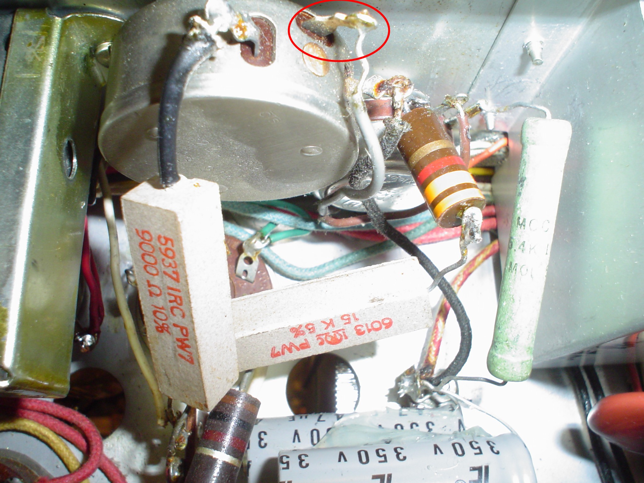
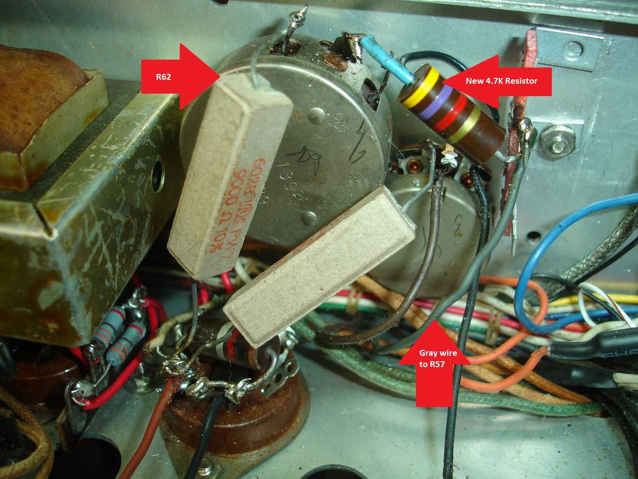
Photos of grid bias resistor installation:
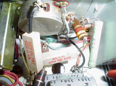 WA1HLR mods grid bias resistor; disconnect this wire and insert 4.7K WA1HLR mods grid bias resistor; disconnect this wire and insert 4.7K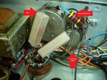 Thanks to David Phillips for showing his Valiant Grid Bias Resistor Installation. Thanks to David Phillips for showing his Valiant Grid Bias Resistor Installation.
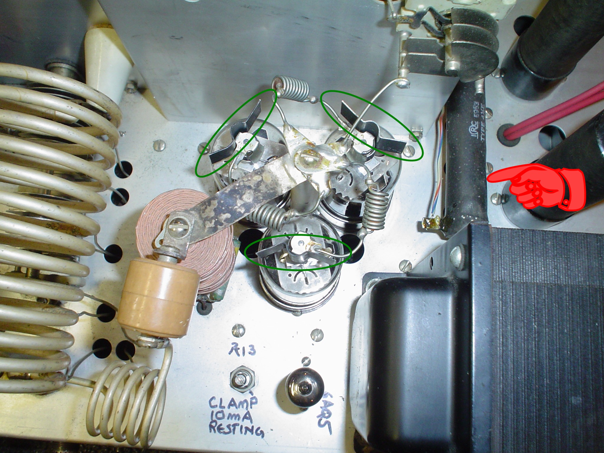
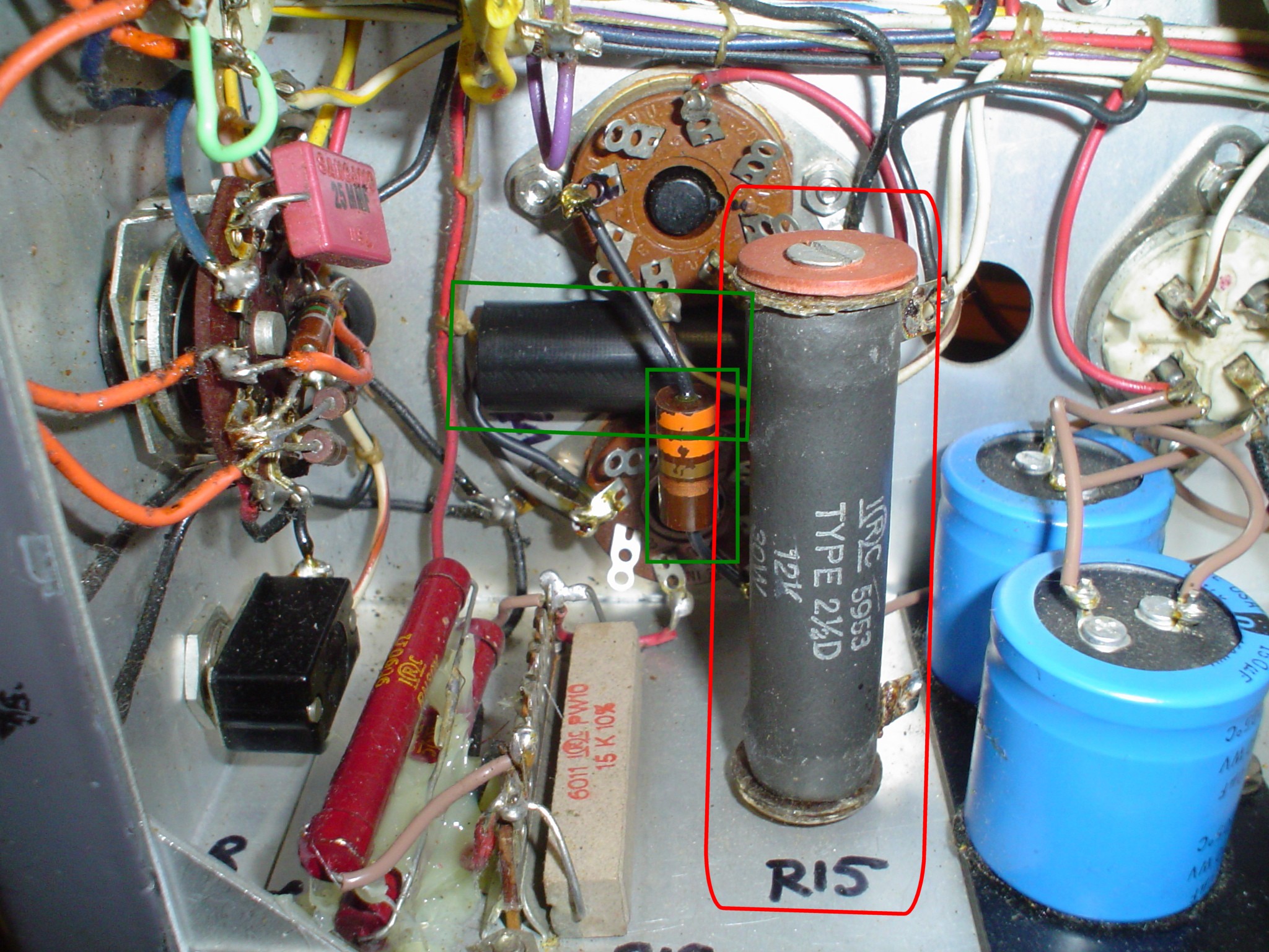
Photos of which resistor to increase in the RF final, click on the photo, the red hand points to the large resistor on the right. This is the one on TOP of the chassis.
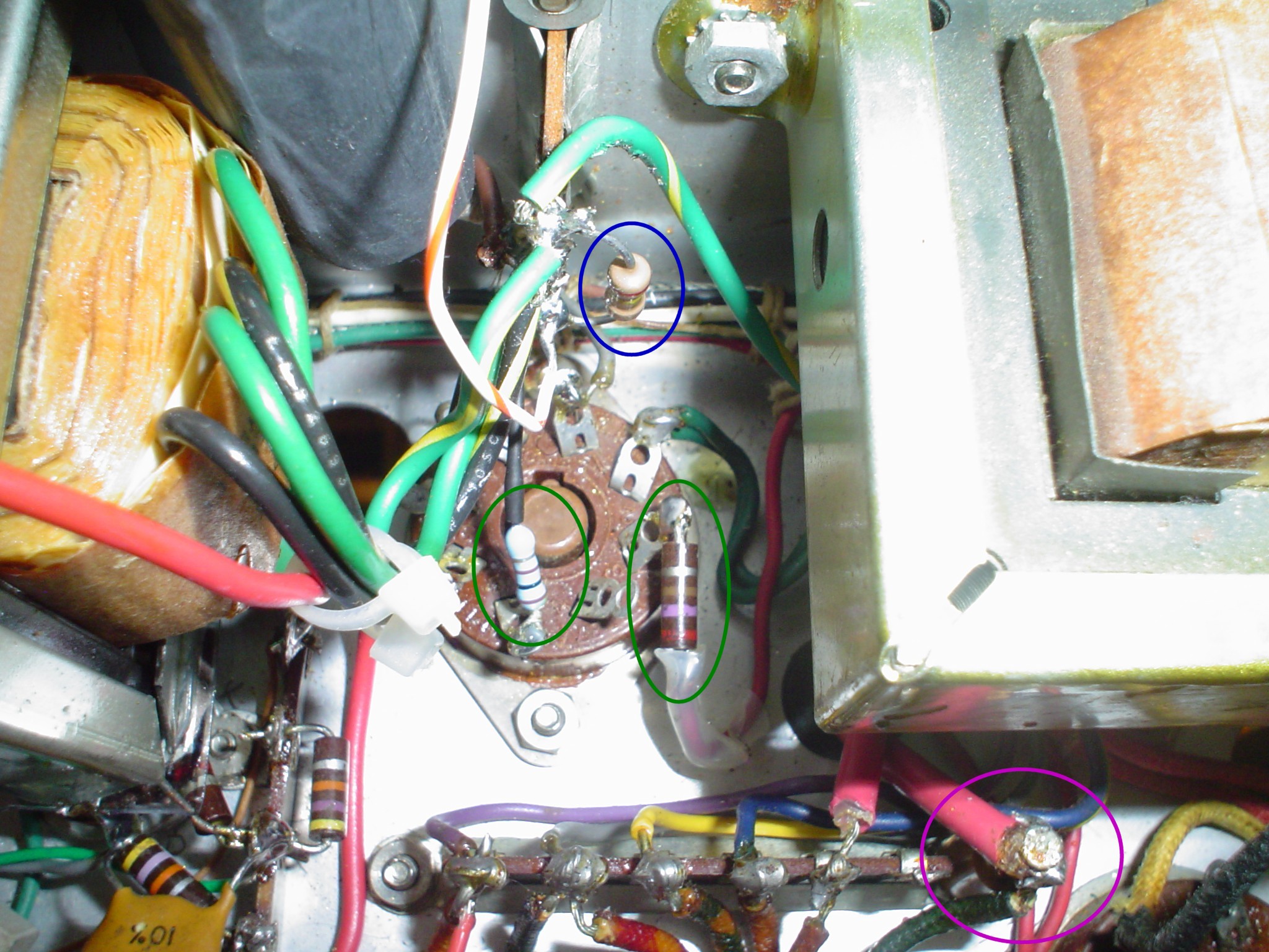
Photos of the capacitor and resistor in the AUDIO SCREEN VR TUBE CIRCUIT.
Click on each photo for detail, and see the boxes and circles highlighting the components added:
This ends my photos and schematics of E. F. Johnson Valiant Modifications by WA1HLR as installed by me. My Johnson Valiant Design and Johnson Valiant Modifications pages give you all the WHY and WHAT of MY work. I have provided the above discussion as an aid to people trying to do JUST TIM"S mods. I am not ripping off his work. I am just showing you how to do it correctly. Good luck with your project.
Important: Do not forget to do the Johnson Valiant Drive Control modification by WA1HLR. Here is how:
/Projects/AMTransmitters/JohnsonDRIVEresistor.html
Also look at my photos and discussion of replacing the "Chernobyl" resistor that always burns up in all the Johnson VFOs:
/Projects/AMTransmitters/JohnsonVFOresistor.html
UPDATE 1/14/2017: "Use correct 124B or P-T156 Hammond transformer in Johnson Viking Valiant Mods by WA1HLR".
There is a lot of confusion resulting from the choice of whether to keep the original Valiant audio configuration (single ended driver stage) with minor mods (W8JI and WA1HLR) or using the extensive mods PUSH PULL DRIVER STAGE contained on my site. I get a lot of inquiries about the WA1HLR Valiant mods; Tim provides a good written description of how to improve your Valiant. I used his mods and added my own. I will provide below, in the next heading, photos and schematics which include his mods, to clarify some ambiguities in the written information. I recommend you do ALL of the Johnson Valiant Modifications by WA1HLR FIRST; THEN replace the Johnson Valiant Driver Transformer with the Hammond 124B or P-T156. This will take you a LONG way. My full replacement with a push pull audio driver circuit is a huge job, and will make smaller but significant improvements, should you care to go to all the extra work.
IF you want to keep the original wiring of the Valiant (while implementing the Johnson Valiant Modifications by WA1HLR), that is a SINGLE ENDED DRIVER. The two sections of the 12AU7 or 12BH7 are connected in PARALLEL for more plate dissipation and lower output impedance. This configuration should use the Hammond 124B or P-T156 transformer. The exact color code of the wiring will be explained to follow.
MY article's schematics are for a push pull configuration of the 12AU7 with a 124E transformer: (click to enlarge)
READ THIS CAREFULLY: THE ABOVE SCHEMATIC IS NOT THE WAY TO WIRE THE SINGLE ENDED VALIANT STOCK CONFIGURATION, the W8JI or WA1HLR mods. USE THE ORIGINAL JOHNSON MANUAL, AND THE COLOR CODES I GIVE IN THE DISCUSSION BELOW. WA1HLR says of the stock Johnson Valiant Driver Transformer:
"The anemic modulator has all it can do to reach 100% modulation. The audio quality is that of two dixie cups and a string." This is substantially the fault of the stock Johnson Valiant Audio Driver Transformer.
About the stock Johnson Valiant Driver Transformer, Chuck Felton, a well known professional restorer of classic equipment, states: "It is the worst thing you could have after a clipper; it's trash." You gotta love a man who calls it the way it is.
For the purposes of all these discussions, consider the 12BH7 and 12AU7 as the same. Principal reason for 12BH7 is it has more plate dissipation. Note that the cathode resistor will probably not be the same for optimum performance, if changing tubes. IF the voltage swing on the plates is sufficient to cause the 6146s to draw about 0.1 mA grid current, indicating class AB2 operation, it will fully modulate the Valiant, and then some. If you find your scope is showing flat topping on positive peaks at the grids of the 6146s before 100% modulation, you are not driving the grids properly. Also experiment as noted below with the step up/step down configurations of windings if you want to; WA1HLR recommends step DOWN. I recommend step UP, with inverse feedback. I give the wiring for the step UP, which is most compatible with the original Valiant wiring, and what I found to work.
After you get it all done and working, you may try some inverse feedback from the grids of the 6146s back to the 6C4 cathode with a high value resistor and a blocking capacitor; this will lower drive impedance and distortion, and make class AB2 work even better. Unless you are really experienced, I do not recommend trying a feedback loop which goes from the RF side of the mod transformer, and goes back before the driver transformer. Some people have done this, but you really need to know what you are doing. W1CKI does this successfully at
http://www.w1cki.net/A%20Speech%20Amplifier%20For%20Everyone.htm
But his design is comparable to mine in MY Valiant Design and Valiant Modification articles, PUSH PULL DRIVER MODE. This discussion is for the SINGLE ENDED DRIVER.
The correct connection for the SINGLE ENDED DRIVER MODE 124B P-T156 is as follows (from website of mfg):
http://www.hammondmfg.com/pdf/124B.pdf
- Red goes to B+
- Blue goes to plate of 12AU7s in parallel (single ended stock Valiant connection)
- Black goes to negative bias for 6146s, with a large condenser to ground like 1000 uF to 2000 uF (observe polarity!)
- Greens go to grids of 6146 tubes, one to each grid. Phasing can be adjusted by swapping green leads. Do not remove the 100 ohm or 1K resistors between the transformer drive and grid of tube, that is oscillation prevention. Further, a resistor of somewhere between 5K and 250K (experiment while looking at a scope for minimum distortion) will load the secondary and provide flatter response.
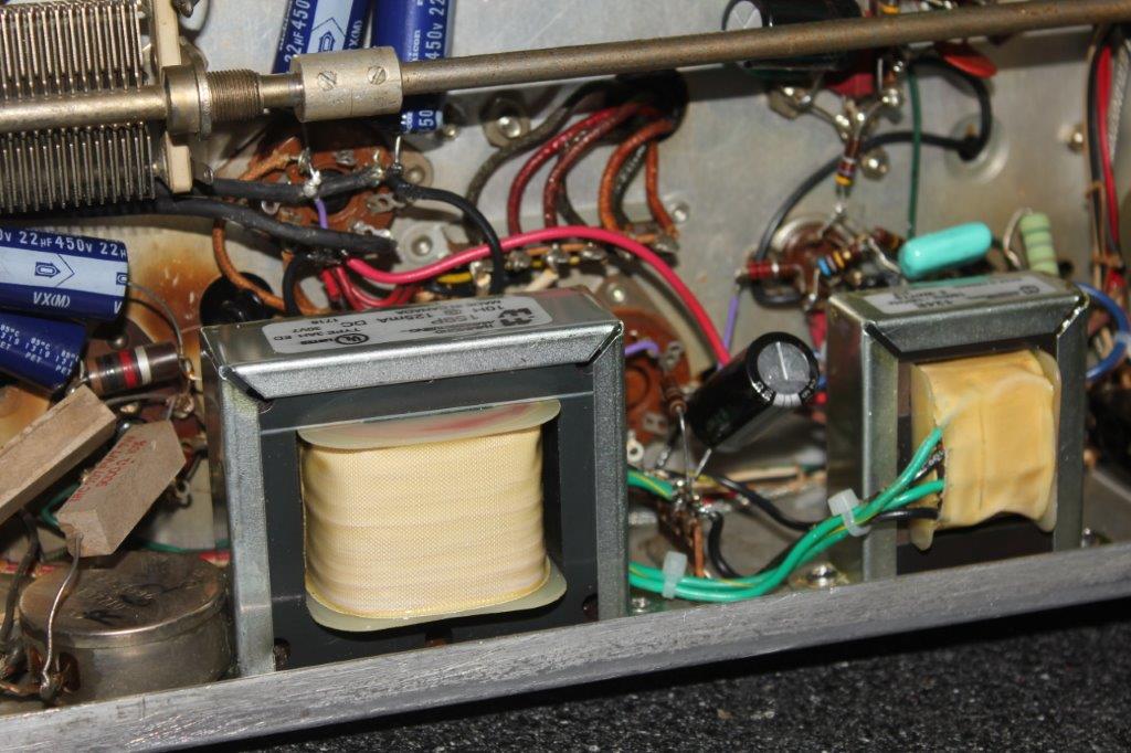
Please note that this is a 1:3 step UP, similar to the original Valiant design. With the existing 12AU7 driver and the stock rated B+ of around 300 VDC, this will provide enough swing on the grids to barely reach AB2 mode in the 6146s. That was a design to prevent ignorant people from destroying the mod transformer or splattering. The 124E is an entirely different beast, for push pull driver stages, as done in the later article. Note that the plates of the driver tube do not tie together, they go to opposite ends of a center tapped primary, and the B+ goes to the center tap. The 124B or P-T156 has NO center tap in the primary. It is for the original single ended Valiant stock configuration. These transformers are larger, but have the same bolt pattern of the original Valiant chassis. See the photos for mechanical considerations.
If you do this, I recommend you change the capacitors W8JI suggests, and leave the rest of the audio alone, including leaving in the clipper to prevent overmodulation and possible modulation transformer damage. Ignorant people rip out the clipper and following splatter filter and do not provide any means of limiting the audio to less than 100%, particularly in the downward direction, which cuts off the RF stage current to zero and removes all resistive load from the modulation transformer. This is a recipe for arcs and possible mod transformer failure. See my extensive photos of arcing problems in the Valiant article that follows. Note: Some of the popular voice processing boxes such as the Symettrix 528E may not provide "limiting" which is effective enough to prevent overmodulation. You may be able to use this, but you must provide a clipper or hard limiter somewhere in the system before the modulation final stage. This is why I leave the clipper in the Valiant, but adjust it so that it only operates on
rare occasions of overdrive. Read my article on SPLATTER for more.
W8JI articles:
Simple, which capacitors to increase:
http://www.hammondmfg.com/pdf/124B.pdf
Extensive data, why the East Coast mod does not work at 100% modulation, don't put a choke in the RF final screen, with 27 eight by ten glossy print color photos and circles and arrows and a paragraph on the back of each one, explaining why your Valiant should not be the victim of a modification "massacree":
https://www.w8ji.com/Johnson%20audio%20mods.htm.
NOTE: W8JI claims that you do not need to change out the driver transformer, and you do not need AB2 to get 100% modulation. Observe his data, read my article and decide for yourself. I found that only 6146Bs that tested "like new 100%" on my tube tester could do full modulation. I prefer to get more life out of my tubes, and my mod delivers that, by providing adequate drive to attain class AB2. I claim the transformer is especially important because it provides the low frequency response to prevent the clipped audio on overmodulation peaks from being differentiated, causing the very overmodulation that it is trying to prevent. See my discussion.
|