|
THIS INFORMATION IS FOR LICENSED HAM OPERATORS. DO NOT TRANSMIT WITHOUT
A LICENSE. SEVERE FINES AND/OR JAIL TIME ARE IMPOSED ON ILLEGAL
OPERATION. FOR LICENSING INFORMATION, SEE:
http://w5yi.org/
http://www.arrl.org/
BEWARE OF THE LETHAL VOLTAGES INSIDE THIS AMPLIFIER!
EVEN EXPERIENCED AND KNOWLEDGEABLE TECHNICIANS HAVE GOTTEN CARELESS AND
BEEN KILLED WORKING ON VACUUM TUBE EQUIPMENT. EVEN SOLID STATE
EQUIPMENT CAN KILL YOU IF YOU DO NOT KNOW THE SAFETY PROCEDURES.
DO NOT WORK ON YOUR RADIO GEAR UNLESS YOU ARE REALLY SURE OF ALL THE
SAFETY TECHNIQUES REQUIRED. THESE INCLUDE, BUT ARE NOT LIMITED TO:
- DISCONNECT THE POWER CORD WHEN WORKING INSIDE.
- DISCHARGE ALL FILTER CAPACITORS.
- BE CAREFUL HANDLING TUBES, ESPECIALLY THE PLATE CAPS.
- REMOVE FRAGILE COMPONENTS WHEN SERVICING, AND STORE THEM SAFELY TO AVOID
DAMAGE.
YOU ARE RESPONSIBLE FOR THE DECISION TO MODIFY YOUR EQUIPMENT, AND NO
LIABILITY IS ASSUMED MY ME OR ANY OF THE LINKS I MENTIONED. THE
SOLUTIONS PROPOSED MAY NOT BE APPROPRIATE FOR YOUR RADIO SYSTEM.
PLEASE DO NOT COPY THIS PAGE WITHOUT CREDIT TO ME. IF YOU WANT TO LINK
TO IT, I WILL UPDATE THE PAGE FROM TIME TO TIME AS I GO FORWARD WITH THE
OTHER WORK. IT WILL BE TO YOUR ADVANTAGE TO HAVE THE LATEST INFORMATION.

The Harbach fan mod has been around for a while. This kit, along with
the capacitor/rectifier kit is a good way to modernize your Heathkit
SB200/201. The fan has high quality bearings and will last a long time. I chose instead to use some 12 VDC fans, which pressurize the final compartment, and provide better cooling. The article covering that is here: /Projects/Heathkit-SB200-fan
Harbach also has fixes for failed antenna relay. My amplifier worked fine, so I only cleaned the relay contacts with a rough piece of paper. USE NO CONTACT CLEANER. It leaves an oily film, and can damage plastic parts, and is not needed. Do not use a file because the contacts are plated, and anything other than rough business cards cut into strips will permanently damage the contacts. I plan to do a power supply capacitor replacement. But the power supply board in my amp is fine, so I am only going to change the filter capacitors, not the whole board. That saves money and a lot of hassle removing the board and replacing it. IMPORTANT: Use 105°C capacitors rated at 5000 hour life or better. It gets HOT in the power supply portion of the SB200. This precaution will preclude premature failure.

Modern 105°C capacitors in stock Heathkit PS Board|
HARBACH SOFT START KIT INSTALLATION, WITH MOV
The Harbach soft start kit installation is described here, with photos. Could you build one yourself? Sure, but the cost savings would not be worth it. The Harbach soft start kit is simple enough for any ham to install, and it looks very professional. I will not repeat the instructions that come with it here, but they are complete and fool proof. There are two versions. I use my amp on 115 VAC, so I bought that one. The only difference between the 115 VAC unit and the 230 VAC unit is the value of two power resistors. So order yours from:
http://www.harbachelectronics.com/main/page_products_sb200__sb201.html

Harbach + 12V fan |
|

With the 12VDC fan mod |
|

With the stock fan |
While you are inside the amp, install an MOV (Metal Oxide Varistor) across the AC line to protect the power supply diodes from AC line glitches. I bought these from Radio Shack. Go to a store that has the parts drawers. I had previously installed one across the AC line BEFORE the switch. This is wrong. I moved it to AFTER the POWER switch. NOTE: Installation shown is for 115 VAC; DO NOT use this configuration for the 230 VAC version. You will have to figure out the 230 VAC MOV installation for yourself. I fed this from a dedicated 115 VAC 20 amp circuit; there is no need with a small amp like this for a 230 VAC outlet. Maybe the 230 VAC was to sell to the international market.
The builder of the kit you have in front of you may have various lead dress, you will have to deal with that. Do not allow for installation that invites shorting from component movement. Do all the resistance checks in the manual FIRST before applying power. When powering up, set the meter to the HI VOLTAGE function. If the HV does not come up immediately, power down. The Harbach mod will cause a relay click, followed by another in less than 2 seconds. This is all the delay you need to prevent damaging surge currents to the 572B filaments and the HV rectifiers. Do tests at each step; do not do all these mods in one sitting. You will have a better chance to identify incorrect wiring or bad components if you do this.

Do NOT install MOV here |
|

Do NOT install MOV here |
|

Correct 115 VAC MOV installation |
GROUNDING OF POWER SUPPLY BOARD AND METER PROTECTION DIODES
One of these amps I was rebuilding would drift Plate resting current (no signal). I was not sure of the cause. I resoldered all of the connections in the bias supply, and replaced all capacitors there. I used film capacitors instead of the original electrolytic for the 2 uF capacitor. This stablized the negative bias, which sets the resting current. I found that grounding the power supply board near where the meter resistors were located helped. Also, the nut holding the meter switch was loose. The switch and meter derive their ground from that switch shaft. I installed the solder lug under the power supply board mounting screw, as shown, to give better grounding. I also installed meter protection diodes directly on the meter terminals. If anything fails, the 3 amp diodes across the meter afford considerable protection; you should always do this on any meter circuits in your transmitters. W8JI has an excellent article on protecting meters. In other situations, you may have to use diodes in series to get the conduction voltage higher (to keep the meter accurate). In the SB200, you only need one set of diodes back to back (to protect both polarities of fault).

Use a film, not electrolytic cap here |
|

Use a new electrolytic here |

Add a ground lug to the PS ground foil here |
|

Install meter protect diodes here |
REPLACE THE RCA INPUT CONNECTOR WITH AN SO-239 FOR RELIABLE CONNECTION
Heathkit's annoying use of RCA connectors for 100 Watts of RF should be dealt with now, if it has not been already. The SO-239s that mount with a nut instead of 4 screws are easier to use.
INSTALLATION OF ARC PROTECTION: SPARK GAPS, ALC CAPACITOR
The availability of new 572B tubes from modern Chinese suppliers has been dramatically improved by RF PARTS. For a period of time, most 811 and 572B tubes were defective from the factory or short lived. At the time, manufacturers were not pulling good vacuum, and resting currents were all over the map. I was lucky to have new old stock Cetrons and some lovely Svetlana Russian made tubes (no longer available). More on this later. Anyway, Heathkit was an economy amp, and did not provide for this arc over protection that is common in modern tubes. Neither did anyone else in those days. Ameritron had to now; fortunately, the parts you need for this project can be obtained from them. This is how to update your SB200, to protect the circuitry. Another reason to do this mod is to protect your transceiver or exciter. Solid state equipment does not like ESD or arcing. A HV arc from plate to grid (and thence the cathode) could get out of your SB200 and fry something in your newer solid state radio. As with lightning protection, nothing can protect you from a direct hit. But you can take steps to reduce the chance of injury, like not standing outside under a tree in a lightning storm. Ameritron uses this technique in all their new tube amps.
First obtain some spark gaps (part numbers at end of this section) and install them from EACH SIDE of the 572B filaments to ground. Use the existing ground lug for the 200 pF capacitors (C14 & 15) from grids to ground. Connect the other end to the filament pin of the 572B. Remove the tubes when you are soldering to the sockets of the 572B. A number of views of this process for both amps are shown below. The builder of the kit you have in front of you may have various lead dress, you will have to deal with that. Do not allow for installation that invites shorting from component movement. Do all the resistance checks in the manual FIRST before applying power. When powering up, set the meter to the HI VOLTAGE function. Do tests at each step; do not do all these mods in one sitting.
Also, move the imbalanced ALC sample capacitor C29 (5 pF) from the right hand (viewed from the back of the amp) 572B grid to the junction of the two 33 Ohm 1 Watt resistors nearby (R21, 22). This is only a 2% imbalance in the original design, but it works one of the tubes harder, and it just ain't right. Get this done while you are in there. This mod is common enough that a previous owner may have taken care of it for you already.

Before spark gaps |
|

Spark gap 1 |

Spark gap 2 |
|

ALC cap move |
Test the amp NOW. Do some tests into a dummy load with RF. If all is well, proceed to the next mod.
INSTALLATION OF ARC PROTECTION: HV RESISTOR, FUSE, METER CIRCUIT CORRECTIONS
This mod inserts a resistor (part number provided at end of section) and a fuse in the HV line from the PS board to the RF choke in the plate circuit of the 572Bs. The resistor limits the rate of rise of peak current from the capacitors in the event of an arc in the 572Bs. The fuse then has a chance to blow in that time, protecting the SB200 circuit, and ending the arc in a reasonable time.
I have seen this mod posted elsewhere, but no one seems to take steps to prevent another fault problem. What happens when the amp is activated, and drive is applied to the grids, but no HV is present? The grids are overdriven, and the tubes are damaged. How do you tell if the fuse is blown without opening the amp? The fix for this is simple: Just move the HV meter sampling resistor(s) (R3, three 4.7 Meg) from the PS board to the FUSED side of the B+ near the tubes. If the meter does not read HV, or the idling current on the PLATE meter function is zero, the fuse is probably blown. Do not apply drive or ground the keying line on the back panel until this is corrected.
First, install a ceramic spacer on top of the existing screw in the location shown. Be sure that the ceramic spacer does not have a hole all the way through it, or an arc inside the spacer could happen. I do not know why they build them this way, but be sure the one you use is built correctly. You will need a shorter spacer, because the bottom of the cabinet it near these components. It could arc to the cabinet or the chassis. Get the spacing half way in between. You may have to dress the main wiring harness to get clearance from this mod as well as the Harbach soft start mod. Study the photos carefully. I had to replace the HV wire in one of the amps; it is red picture tube anode wire rated at more than 35 KV. I salvaged it from a junked monitor. Quadruple check anything you have done here for safety. Be sure all capacitors are discharged before working on the amp.
Once you have the resistor and fuse holder wired into the HV lead, relocate the R3 assembly to connect to the tube side of the new fuse. The meter now reads the voltage applied to the 572Bs, not the output of the PS board.

Ceramic spacer |
|

New series resistor & fuse 1 |
|

Fuse 2 |

Fuse 3 |
|

Meter resistor, harness dress 1 |
|

meter resistor, harness dress 2 |
HV series resistor |
|
Lead dress avoid Harbach |
|

High voltage wire replacement |
PARTS NEEDED FOR SPARK GAP AND HIGH VOLTAGE RESISTOR MODS
IMPORTANT - DO NOT CHANGE VALUE OF 200 PF CAPACITORS GRID TO GROUND
When reading on the internet, I found some references to low drive on 80 meters due to grid to ground capacitors being too small in value. Here are some:
VERY thorough analysis and step by step instructions:
http://kg5oid.com/sb200-project-rebuild/index.html
Great photos of gassy tubes and discussion:
http://kg5oid.com/odds-ends/gas.html
My test data did not correlate with that. I found "fur" on the scope pattern while trying to get enough drive into the SB-200 from my TEN TEC 546 OMNI, and other evidence of instablility when the 200 pF was changed. The SWR on the meter monitoring the SB-200 output jumped up dramatically at some occasions. That is a certain indication of output on a frequency other than desired.
The purpose of the 200 pF capacitor is to resonate with the internal very long grid leads inside the 572B tube. LOOSEN THE GROUNDING LUG SCREW AND MOVE IT TOWARD THE TUBE AS CLOSE AS YOU CAN. SHORTEN THE LEADS TO THE ABSOLUTE MINIMUM. Replace any rectangular mica capacitors with the newer maroon dipped micas; they are sealed better. (Test the 200 pF capacitors for shorts. These can fail if there is an internal tube arc due to gas from plate to grid. If they short, no cutoff or operating bias will be on the tube, and high plate current may cause damage.) W8JI has suggested that manufacturers should build 572Bs with a second connection to the grid for the unused pin on the socket for lower inductance to the ground connection. That would be a great idea, if many amps did not also use that pin for a tie point. Collins (30L1), as well as the legendary Bill Orr came up with the 200 pF to ground idea. You will have to decide who you wish to believe. I went back to the 200 pF after trying a much higher value. Here are the comments from the web:
Please don't change around what I am saying. You know I never said the .01's "neutralize" anything, so let's stop "inventing" statements.
I **think** you are saying or implying the 200 pF caps neutralize the amplifier on ten meters.
A capacitor to ground from the grid cannot neutralize an amp. All it can do is series tune the grid path to ground. This can make the grid grounding get much better at one frequency, and that does improve input-to-output isolation at one frequency range, but all other frequency ranges get worse and the lower in frequency we go the worse it gets! It is only near and above the SRF that grid to chassis impedance is reduced.
With 200 pF on ten meters, it would take ~.16 uH of inductance from the grid element through tube leads and the cap to the chassis. That would take about six to seven inches of .05 inch diameter grid lead with 200 pF. The actual series resonance of the 572 and capacitor in the SB200 is up around 70 MHz or so. You'll see a decrease in feed through from maybe 60 MHz to just up above the FM band. Below 40 MHz or so the feed through gets worse, not better. Above the FM band not much changes......
I think what you might have seen is the mica cap does help stabilize the amp by grounding the grid better on lower VHF, so if the wiring is sloppy or the parasitic suppressor not up to snuff the cap can help....but it just kills the grid grounding below mid-HF and even hurts it on ten meters.
Again, your mileage may vary. The most significant statement is the last line of the quote; the 200 pF gives better VHF stability at the expense of 10 meter performance. I will take that trade. And the parasitic suppressors ARE working very hard in this amp, which is why they fail if driven hard on 10 or 15 meters. I do agree that with better tubes than the 572B, a very short strap directly to ground would be theoretically better for stability. In that case, the operating and cutoff bias would have to be provided via the cathode circuit. This would be inserted in the center tap of the filament winding to ground. A simple Zener would work. Many good commercial and home brew amps use that exact circuit. For cutoff bias, simply opening the cathode circuit would NOT work. This would possibly put high voltage on circuit elements that were not intended for that use. For example, the 6.3 VAC filament winding is NOT insulated for anything other than GROUND POTENTIAL. With modern 572Bs, some low frequency oscillations result (as noted by W8JI), due to Chinese tube manufacturing tolerances. For Tom's Ameritron amplifier designs, there are fixes on his website to compensate for those problems. I did not try any newer style tubes here, so I cannot comment on any problems resulting from using Chinese tubes. Neither did I contemplate "hacking" this amplifier with unnecessary modifications. I have repaired a number of these, and did not find dramatic measures necessary to obtain nominal performance. It is true that others have obtained some increase in output power, but when evaluated for the net effect in the other operator's S meter reading, the improvements are not worth the effort, in my opinion. What I have provided on this page is primarily a method to get the amplifier working properly and modernize the protection circuits and cooling.
During this experiment, I did have more than expected SWR going INTO the SB-200 also. I tried the 200 pF capacitor fix, thinking that it might correct the SWR problem. It did not, and introduced new instablility problems. The SWR turned out to be a problem with the input tuned circuits. The SWR was finally traced to a bad solder connection on the capacitors in the input circuit on 80 and 40 meters. Once those were properly soldered to ground, the SWR problem went away, and I had correct drive. During the troubleshooting process, I had to test the input SWR of the amplifier.
TESTING & ADJUSTING INPUT SWR OF GROUNDED GRID 572B AMPLIFIERS - SB-200
If you have more than expected SWR going INTO the SB-200 as indicated on your transceiver SWR meter, there may be a problem with the SB-200 input network. (If your SB-200 output power is abnormally LOW for normal indicated PLATE current on 10 and 15 meters, check your parasitic chokes FIRST. It is normal to get 100 to 150 watts less on 10 meters than 40 meters, due to inherent amplifier design issues.) I devised a method that you may find useful to troubleshoot or tune the input network without energizing the amplifier or risking tube damage during tests. I have tables below to show the results for various values of simulation resistors. Be sure to use old fashioned CARBON or OHMITE OX or OY type non inductive resistors. KEEP THE LEADS VERY SHORT ON THE TEST RESISTORS. You are working with radio frequencies, and a little more than half an inch introduces inductance which detunes the circuits. I disconnected the SB-200 from everything, especially the AC power line. Make sure the High Voltage is discharged. Place a thin piece of cardboard in the switch through relay to place the contacts in the transmit position. This closes the contacts from the input connector to the input tuned circuits, and thence to the 572B cathodes. Use an MFJ antenna analyzer to test the SWR looking into the input connector, with the test setup described above. Test all the bands, tuning through the band from end to end, to take data on the SWR. Theory suggests that the correct impedance of the 572B cathodes is somewhere between 100 and 500 ohms. In retrospect, I should have taken an additional data point at 390 ohms. If you are going to adjust the input coils, 270 to 300 ohms would be the best choice on the SB-200. Other grounded grid amps will require you to experiment with the correct input impedance to simulate for varying values of grid current. I tried various values from cathode to ground, and think it lies in the vicinity of 250 - 300 ohms. Keep in mind that a substantial portion of this highly variable load is due to this being a class AB2 amplifier. Note that without the resistor to ground from the cathode, input SWR is quite high. Input resistance (impedance) varies widely, depending on drive level, as well as final plate tuning of the grounded grid amplifier. The grid current varies proportionally with the plate current as the loading control is changed. It is better to use tighter coupling (reduce pi network output capacitance), for less chance of instability and better linearity. See W8JI essay on how to tune a linear for more information on that. When the grid draws more current, the impedance seen at the cathode goes DOWN. So lower resistor values simulate the higher grid current condition of driving the amplifier harder to get full output. Input SWR match would be most important under that condition, to avoid fold back in the transceiver. The Ten Tec OMNI 546 does not use ALC, nor does it fold back under SWR (a feature not offered on radios of its age). I do not know of anyone who has posted this information. You might like to do this test with your amp, even if it is not an SB-200, since the technique is transferrable to any grounded grid or class AB2 amplifier. Here are my test results:
SB-200 INPUT SWR
| BAND | RESISTOR | FREQUENCY | SWR |
|---|
| 80 | 100 | 3.26 | 2.2 |
|---|
| 220 | 3.71 | 1.4 |
| 470 | 3.9 | 1.1 |
| 40 | 100 | 6.6 | 1.5 |
|---|
| 220 | 7.01 | 1.2 |
| 470 | 7.11 | 1.3 |
| 20 | 100 | 13.3 | 1.1 |
|---|
| 220 | 13.8 | 1.4 |
| 470 | 13.8 | 1.8 |
| 15 | 100 | 18.6 | 1.1 |
|---|
| 220 | 20.1 | 1.7 |
| 470 | 20.2 | 2.0 |
| 10 | 100 | 29.3 | 1.2 |
|---|
| 220 | 29.3 | 1.4 |
| 470 | 29.3 | 1.6 |
|
SB-201 INPUT SWR
| BAND | RESISTOR | FREQUENCY | SWR |
|---|
| 80 | 100 | 3.45 | 1.8 |
|---|
| 220 | 3.81 | 1.3 |
| 470 | 3.89 | 1.5 |
| 40 | 100 | 7.09 | 2.0 |
|---|
| 220 | 7.00 | 1.4 |
| 470 | 7.11 | 1.1 |
| 20 | 100 | 12.41 | 1.3 |
|---|
| 220 | 14.0 | 1.1 |
| 470 | 13.9 | 1.6 |
| 15 | 100 | 21.4 | 1.3 |
|---|
| 220 | 22.1 | 1.1 |
| 470 | 22.4 | 1.4 |
Note that the SB-200 tunes much more sharply on 10 meters.
|
|---|
This revealing test demonstrates why your transceiver can have problems with the varying SWR presented by a class AB2 grounded grid amplifier. The slugs were sealed with wax in the SB-201. That one appeared to be competently assembed and not tinkered with. I did not attempt to adjust them, since I was not having problems with this amplifier. The slugs in the SB-200 were mostly seized, with the exception of the 80 meter slug. I was having problems with 80 meter drive, so I tuned that slug for the lowest frequency I could obtain, which seemed a bit high, at the top of the band. The Q of these circuits is about 2, so it is not sharply tuned (except 10 meters). I suppose that I could have added turns to the 80 meter coil, or paralleled the capacitor in the 80 meter network, to tune it closer to mid band. In final test with RF applied, the transceiver now "liked" the SB-200 and drove it properly. That was the result I was after, and there was no need to do anything more.
I firmly believe in avoiding the philosophy: "If it ain't broke, fix it til it is."
Also, get something working as originally designed, before you go modifying it.
The SB-200 has a long history, 15 years of successful production and use. There are no documented instability issues, unless you fail to check the parasitic supressors or operate it correctly.
The test result tables above may be of value, if you are repairing an SB-200 that some one has modified (perhaps for 11 meter use) or the coils have been adjusted from factory settings.
ADDITIONAL NOTE: Be sure to test the filament voltage (receive mode OK) right at the tube sockets. It should be near 6.3 VAC. If it is not, suspect bad high resistance wiring or solder joints. There is a lot of current drawn, and it does not take much resistance to dramatically lower filament voltage - and tube life. The lower emission resulting from this will make the amp hard to drive and lower output. These symptoms will emulate tubes with low emission at end of life. If you ignore this, you may buy new tubes by mistake. Pay special attention to the grounding of the filament center tap. You may install a separate wire from the inadequate grounding on the AC screw terminal strip (from a phenolic spacer) to a new ground lug mounted to the chassis.
PARASITIC CHOKE FAILURE & HOW TO REPAIR PLATE CAPACITOR ARCING
While this discussion is about the Heathkit SB-200, the information here is equally applicable to ANY tube RF amplifier. The technique of using a non-inductive resistor in parallel with a low inductance RF choke in the plate circuit of a vacuum tube is ubiquitous in RF amplifier design since before the 1950s. Some of the sources referenced in this article address the design parameters that go into selection of the correct values of components in the LR network. I limit this article to getting your radio or amp running again, as originally designed. If your SB-200 output power is abnormally LOW for normal indicated PLATE current on 10 and 15 meters, check your parasitic chokes FIRST. This is often the first symptom of change of value in the 47 ohm carbon resistors in the center of the parasitic choke. It is normal to get 100 to 150 watts less on 10 meters than 40 meters, due to inherent amplifier design issues. If it exceeds this loss on 10 and 15 meters, check the parasitic choke resistors BEFORE the amplifier starts to oscillate and arcs destroy your plate tuning capacitor or band switch. This statement is valid for both the SB-200 and SB-201.
Lead dress is an important detail that must not be ignored. Many of the instabilities that cause parasitics are lead inductances and stray capacitances inherent in the tube. This is particularly true of large glass transmitting tubes, but it is just as true of the 6L6 in RF applications above 7 MHz. If you have 2 or more tubes, the parasitic chokes should be oriented approximately 90 degrees to each other. If the tubes have been changed by a previous owner, they may not have done this correctly. This reduces inductive coupling between them, which upsets the choices of values and effectiveness of the parasitic suppressor circuit. If the manual for your particular equipment shows some different lead dress or choke orientation, follow it scrupulously for best results. Perhaps you can find photos of the interior of your equipment on the internet that will give you guidance, if there is no manual available.
See W8JI discussion about the Parasitic Suppressors, and other important topics relating to the SB-200 amplifier.
If the color codes on the Parasitic Suppressor resistors are unreadable due to discoloration, they are probably fried. You can carefully remove them and separate the coil from one end of the resistor to test them. They usually go up in value. Replace them now, not after the amp becomes unstable and damages something. If they are still good, just wrap the wire back around the resistor, resolder it, and put it back in.
The common damage is the band switch (Harbach has the switch wafers) and the Plate Tuning Capacitor (RF parts). Photos below show damage caused by arcing due to instability. If you see this sort of damage, it is most likely caused by bad parasitic choke resistors. I do not understand why anyone would abuse a nice amp like this and let it continue to arc until it is unuseable. If you are patient, you may be able to use emery boards (Sally's Beauty Supply), progressing down to 400 or finer. A smooth finish is essential to prevent future arcing. Removing a portion of a bad plate will not hamper the higher bands, and in most cases will not influence maximum capacitance available enough to prevent amplifier use on 80 meters. I began treating this capacitor, as you can see, but obtained a good tuning capacitor from a junker amp. I may finish repairing the damaged capacitor, just for the experience. Some people disassemble the capacitor into individual plates. I am not sure if this one can be treated that way. GOOD NEWS: RF PARTS now carries an exact replacment Plate Tuning capacitor for the SB-200. Apparently this problem is so common that there is enough of a market that it economically justified making some again.
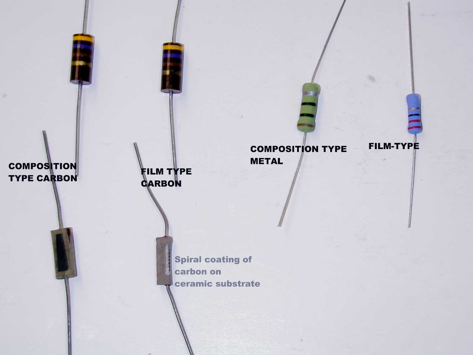
See also the discussion on repairing the original parasitic suppressors. Mine measured over 300 ohms and were cooked. I took the precaution of buying a large quantity of 47 Ohm carbon resistors. Do NOT use modern inductive resistor types, or you may severely damage your amplifier!!!! There are now good replacement non inductive resistors available from common sources such as Mouser. At least one resistor manufacturer, Ohmite, sells one and two watt non inductive resistors. They are ceramic composition 10% resistors in the correct resistance range. Choose the wattage that matches your application, and be sure you do not change the length or diameter of the coil. Obviously, if a higher wattage will fit inside the original coil, use the bigger one. These resistors are Ohmite OX and OY series.
You should decide for yourself which approach you should take to that problem. I am not going to endorse one or get involved in a debate with somebody about why I did it differently. This is an example of the importance of carefully researching your mods on the internet, to be sure you are comfortable with your final choice.
IMPORTANT: After repairing the Parasitic Suppressor RF choke resistors, be sure to do neutralization procedures, if your amplifier or transmitter employs it, before placing it back into operation.
Here is a test procedure for gradually bring the amplifier up to operation. (Use procedures in the original equipment manual, if they show them.) First, try a lower band, such as 40 meters, to see it it works properly there, to eliminate any other problems. USE A DUMMY LOAD. You do not need your spurious radiation splashing all over the HF and VHF spectrum during testing. Then progressively move up to 20, then 15, then 10 meters, being careful to observe all operating characteristics. Any unexpected sudden jumps in grid or plate current should be explored before placing your repaired equipment back into service. Maybe there is a loose ground connection or screw somewhere. Definitely do not ignore arcing. That will only lead to catastrophic (expensive) failures.
Test 1: Connect a small dummy load (5W) to the INPUT connector of the amp. Connect a power meter and another dummy load rated for your amplifier to the output. Apply B+. If there is a two position (SSB or CW or HIGH/LOW) switch, do it in the lower power position first, then repeat it in the high power position. Gain can change with plate voltage, and oscillation may happen on the higher plate voltage. Working up from the lowest band, try all positions of Plate and Antenna Loading capacitors. Any unexpected sudden jumps in grid or plate current or indications on the power meter should be corrected before proceding to the next step. If you burn out the low power 50 ohm load on the input, imagine what this experiment could have done to your expensive transceiver.
Test 2: Connect the amplifier to your transceiver or an expendable or sturdy (tube) RF source, with variable output power. Connect the amplifier output to a power meter and a dummy load rated for full output. Observe all duty cycle limitations of your amplifier and dummy load. Output power should be normal. Most large glass tube amplifiers do not deliver the same power on 15 or 10 meters that they develop on 40 meters. Ceramic external anode tubes generally do better on 10 meters. Most amplifiers do not deliver the same power all across 75/80 meters (due to changing plate circuit Q). There was one commercial amplifer back in the day (four 811s) that used three band switch positions to deliver the same Q on CW, midband, and phone. Most all modern amplifiers are a compromise that sacrifices operating efficiency and harmonic reduction, by using only one band switch position for 80 meters. Read up on it in the ARRL Amateur Radio Handbooks printed before 1969. Then and only then, proceed to Test 3.
Test 3: Wait until there is a time for low band activity. Example: 80 meters at noon. 20 meters after 9 PM during low sunspot cycle. Carefully operate the amplifier in all anticipated modes (SSB, CW, digital), starting on the lowest band, proceeding to the highest band. Preferably use a resonant dipole or vertical cut for that band. Be aware that an antenna matcher and open wire line can present wildly reactive loads to an amplifier or transmitter. Any tendency to instability will be multiplied by that configuration. But if that is how you roll, operate it as you will in real life. But do your tests at a low activity point for that band. Get a local ham to monitor your signal and give you observations on 2 meters or by telephone. Have him tune off the signal while keying CW or talking on SSB. Check for key clicks, splatter or buckshot. While these are usually artifacts of the deficiencies of the transmitter (not the amplifier), they can also be signs of marginal stablity, assuming you have properly adjusted the amplifer loading. An AM transmitter can break into parasitics at either high or low modulation peaks. If possible, monitor your signal with a scope for fuzziness on peaks or minimums under these conditions. CLUE: On a resonant antenna, if the SWR is not as expected, you may have RF output on a frequency on which the antenna is not resonant.
Test 4: Operate normally. If there are significant variations in output power from published specs, there may be mistuning or damaged components in the input matching network. Read your manual and follow its recommendations. A touch up of the input circuit tuned slugs may favor your favorite mode. Many people optimize phone and take what they get on CW, since the need for more signal is generally on phone. Your transceiver will probably just fold back on SWR on CW and be OK, but you will still get some useable power gain anyway. Some people using solid state transceivers use a small tuner in the input circuit. But you should do so with caution, especially on the upper bands. Sometimes using a small transmatch in the input side of an amp may cause instability. You are inserting a reactive network in the input of the amplifier which has a similar tuned network in the plate circuit. You have created a TPTG oscillator. Look it up in the older pre 1960 handbooks. Some of the older handbooks or amplifiers (Heathkit Warrior) from that time could be improved by an external (low pass) LOW Q Pi network that could be fixed tuned for each band. But be careful to select the matching band on the transceiver, matching network, and amplifier. Avoid a generic T match (high pass) tuner that has to be adjusted each time you change bands. Do you really want 3 more knobs to twiddle during tune up? That puts a lot of stress on the output tubes. Photos at the bottom show the damage to the plate tuning capacitor. This one is pretty bad, possibly beyond saving.
Good luck with your amplifier repair.

Lead dress on parasitic chokes 1 |
|

Lead dress on parasitic chokes 2 |

Lead dress on parasitic chokes 3 |
|

Lead dress on parasitic chokes 4 |
SIMPLE COOLING TRICK IN THE SB200
Get some more extra long screws and spacers for the feet on the SB200. Put them on both the front and back to raise the whole amplifier up for better air circulation. Be sure to inspect the interior of the amplifier for wiring and components that can come into contact with the longer screws. Shorten the screws if necessary, and reroute any cable harnesses or components.
COMMON TUBE FAILURES AND TUBE REPLACEMENT IN THE SB200
One way to tell a tube is bad is to put it in a tube tester. If your tester will set up for an 811, it will also test a 572B. The filament drain is the same.
Tubes can be visually inspected for obvious faults. One feature of vacuum tubes is the "getter". This shows up as a silver coating in one area of the tube, on the inside of the glass. A good getter is shiny and silvery. A bad getter can be brown, dull gray, white, or even have a patch missing. This is sure indication that the tube is gassy and unusable. Installing such a tube in your SB200 will result in arcing from the high voltage supply inside the tube and will probably damage your amplifier and/or any equipment attached to it. There are ways to test for high voltage performance, that do not use a tube tester or plugging them into an amplifier to see if it burns out the amplifier; they employ a home made test fixture, which can also be used to recondition tubes that have been sitting on the shelf for a while. This, and other SB200 information can be found at:
http://www.crompton.com/hamradio/heath/sb200/sb200.html
Here are some bad tubes in photos. A 572B that has a getter that has gone white, indicating gas. A 6146 that has a bad getter. A 6146 that was run at too much plate power input. The plate became hot. Then the glass began to melt, and formed a sharp melted glass portion pointing to the plate. As the glass stretched, it formed a hole at the end. Unable to contain the vacuum, it began to arc. The transmitter was probably damaged as a result, along with an expensive tube. NOTE: Heathkit DX-100 and Apache rigs were prone to this because the manual told you to run the finals at CW ratings when in voice mode. This can also happen with the Heathkit Warrior 811s when running RTTY or AM linear mode. The manual is just plain wrong. The 811s will take a lot of abuse in short duty cycle modes like SSB or CW (if you do not send long dashes). Ameritron gets away with it. 6146s and 811s should NEVER show any plate coloration. On the other hand, a 572B will show dull red when running at full ratings. It was built to do that. A long "faaaaiiiive" will show red dimly in SSB mode. It is still not a good idea to push them for a long time that hard for long life. It really does not move the other person's S meter when you run them 20% over ratings. Back off the drive, and as long as you do not reduce it by 3 dB, the other station will never know. Go easy when running AM linear or RTTY high duty cycle modes.
Here are some good tubes in photos. There are some regular vintage Cetron 572Bs as originally supplied by Heath, still OK after all these years. There are some beautiful Svetlana Russian 572Bs. Note the ceramic base on the Svetlana. There is also a ceramic spacer on the plate cap. The envelope is smaller in diameter. Some people mistakenly believe that a Svetlana 572B or 811A is not rated for the same power. The glass envelope on a Svetlana 572B is high temperature transmitting tube glass. It can be closer to the hot plate without melting like the 6146 shown above. Look inside at the size and thickness of the plate structure. That is where the power rating is determined. The smaller envelope is good, not bad.

|
|

|
|

Nice silver getter |

Svetlana ceramic base |
|

Ceramic spacer on plate cap |
|

Smaller envelope, transmitting glass |
RESOURCES FOR SB200 AMPLIFIERS
|


