UPDATE 8/25/22: The best method of day to day monitoring of your AM transmitter might not be an oscilloscope style display.
It might be the new K7DYY Modulation Monitor, with analog meters for separately showing
negative peaks, positive peaks, and carrier output.
I am happy to report that there are two new entries in the ham market of RF monitor scopes. WA7PRC brought these products to my attention.
This is an excellent system, but needs a computer to operate and display it. If you are using an SDR for your AM or SSB station, that may not be a problem. Check it out at:
http://www.radioassociates.com/.
A completely self contained monitor scope, in two different display sizes and feature sets:
http://www.telepostinc.com/.
He also makes a panadapter. There are alternatives such as an SDR dongle. My FT-950 had a very expensive DMU that provided a band scope as an option. Many of the modern radios provide some kind of band scope as standard equipment. Indeed, the FTDX-1200 (descendant of the FT-950) includes a spectrum scope.
http://www.yaesu.com/indexVS.cfm?cmd=DisplayProducts&encProdID=9D00B8E5727EF1E6778041A8B0133A22&ProdCatID=102.
I have not had the resources to acquire either of these monitor scopes (links above), or to visit a shack where they are in use. So I cannot comment on my personal experience. However, I am glad someone has decided to fill the void with a badly needed product. I prefer a stand alone product that does not require a computer to operate it. One of these might wind up on my AM operating position.
Why use a specialized monitor scope for your transmitter? While you can put a larger bench test oscilloscope on your desk with the rig, it does not have some of the features needed (audio tone generator) and you will have to build an RF sampling box to grab the signal from your transmitter. Here are some of the vintage equipment choices available:
Once in a great while, you will see a Central Electronics MM-1 or MM-2 scope at a swap meet. These are a great "old buzzard" scope, and I have one I am refurbishing for my AM station. When you use it in AF trapezoid, it actually turns off the beam in receive mode! Way ahead of its time. Ideal for phasing SSB rigs. But if you buy one, be prepared to do a lot of work bringing it back to life due to age. If you acquire one of these, there are manuals available reasonably priced. I plan to salvage a graticule from a junked bench scope. The Central Electronics did not have a graticule, but I can add one, if I can get it working again. I will provide a separate photo and how to repair article once I get into it. Here are repair tips:
http://www.ce-multiphase.com/tech-info-mm.html
and the schematic: http://www.ce-multiphase.com/mm1-schematic.pdf
The Heathkit HO-10 uses compactron tubes. These are going to become scarce, if they are not already. I no longer stock them for service or my own equipment. I sold all of them either with rigs that contained them or the remaining tubes went to a tube dealer. The HO-10 has high voltage on focus control, which can cause problems. Also, if you need to replace that control, it may be hard to find.
The Heathkit 610 also has compactron tubes in it. A beautifully restyled unit, rebuilt for Collins lovers is available, complete with a paint job to match the Collins gear. The back panel attenuator of some of the Heathkits is a PITA. The HV insulation on the intensity control (plastic shaft and extension) makes a replacement hard to find. Probably better to use an insulated shaft coupling. But Heathkits are popular, and there are a lot of them out there. One Heathkit owner did a clever mechanical modification to put the attenuator on the front panel. It took careful work to do this. WA7PRC comments:
The XMTR ATTEN rotary switch is on the rear apron, and should be on the front panel. It's OK where it is, as long as you never change bands and/or power level. Otherwise, it should be moved to the front. I accomplished that with a little lathe work. Photos and text are on my Flickr page (shortcut:
http://www.tinyurl.com/wa7prc-sb610). A plus is that a hole on the rear apron is vacated, allowing for the missing ASTIG control to be added. The circuitry can be cloned from the SB-620.
Heathkit SB-614 is all solid state except for the display tube. It is disappointing. First, the magnetic shielding is missing on the display tube. That means if you mount it near a transformer (your linear, your exciter power supply, a keyer with a transformer in it) your display will be modulated by the field of the power supply. It is hard to find a spot on your desk to place it where this is not a problem. Second, the manual cautions you not to have a display that exceeds 4 major divisions in height (though the graticule is 6 divisions high). Damage to the vertical deflection amplifier will result. While these are popular with the matching Heathkit station of the era, I have one and have replaced it with something else. I may put it on my test bench, in a spot that is away from magnetic fields. Or I may try to put some sheet steel inside to tame it. Or it may go up for sale.
The Kenwood SM-230 and Kenwood SM-220 are truly elegant engineering execution. I covet these. However, the price of them is out of reach. The Kenwoods are quality made, and the best available vintage monitor scope, if price is no consideration. If you can find one at a reasonable price, buy it.
WHAT IS THE BEST SPECTRUM SCOPE? THIS ARTICLE IS ABOUT MONITOR SCOPES.
Eham Reviews rates these less than a 5.0. I believe that is unfair. Some people wanted an older scope to work with a newer rig in the Band scope mode. These Kenwoods are obsolete for that feature only, and clumsy to use for a band scope. The phosphor is low persistence, optimum for monitor scope mode; for a band scope, a longer persistence phosphor would have been better. None of the other scopes (Heathkit, Yaesu) even attempt to offer band scope as a feature, in the same package. The graticule is OK for transmitter monitoring, but useless for a band scope. Also, the cables and set up is very different between the two modes of transmitter monitor scope and the receiver connections for a band scope; there is no quick change over between modes. Forget the band scope function, and focus on the great monitor scope sitting in front of you. It was ahead of its time, and the panadapter did not work as well as modern ones. It was first generation. When people try to adapt it to a modern rig, it gets even worse. But it is still the cadillac of contemporary monitor scopes. A high persistence CRT or storage CRT is easy to burn with a repetitive trace. Most hams would not know that and probably put a brown horizontal line on it the first time they used it.
Heathkit offered a separate spectrum display, The SB-620. Read about it here:
The monitor scopes of this vintage did not offer good spectrum analyzer performance, or used unobtainium high persistence phosphor CRTs.
Most of this vintage of monitor scopes also offered a RTTY tuning aid, the cross plot of the output of the two tones as detected. Whether that feature works well is also not a subject in this article. This feature is useful only to the truly old buzzardly RTTY modems that used surplus 88 mH toroids from the phone company. Back in 1968, I worked on a RTTY modem for Bob Weitbrecht that was sold to hearing impaired for using regular telephones, so I know that technology. Modern hams using a Tigertronics or similar digital mode radio interface would have no uses for such a scope feature. I only bring it up here, since the side issue of band scopes has come up. None of these features is relevant to the question: "What is the best monitor scope?" That is why I essentially ignore them.
BACK TO MONITOR SCOPES TOPIC
The Yaesu YO-100 and YO-101 Monitor Scopes are a good choice. The YO-101 is a solid state version of the YO-100. It has all the functionality of the others. It generally sells used for the same as the earlier Heath scopes. Check the types of tubes used in the YO-100; I do not know what it uses. Steer clear of compactrons, unless you have an unlimited supply in hand.
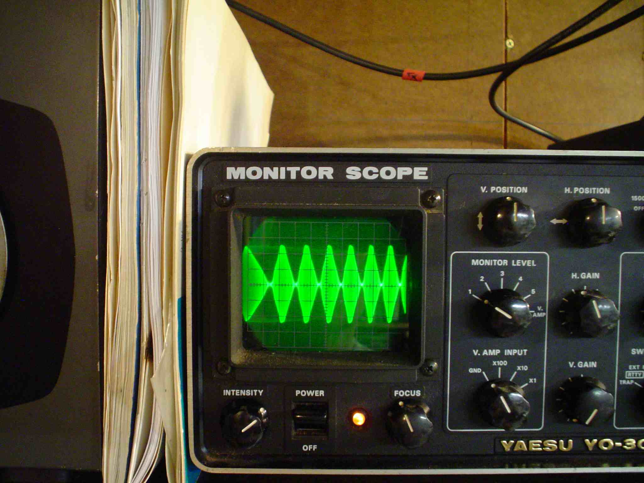
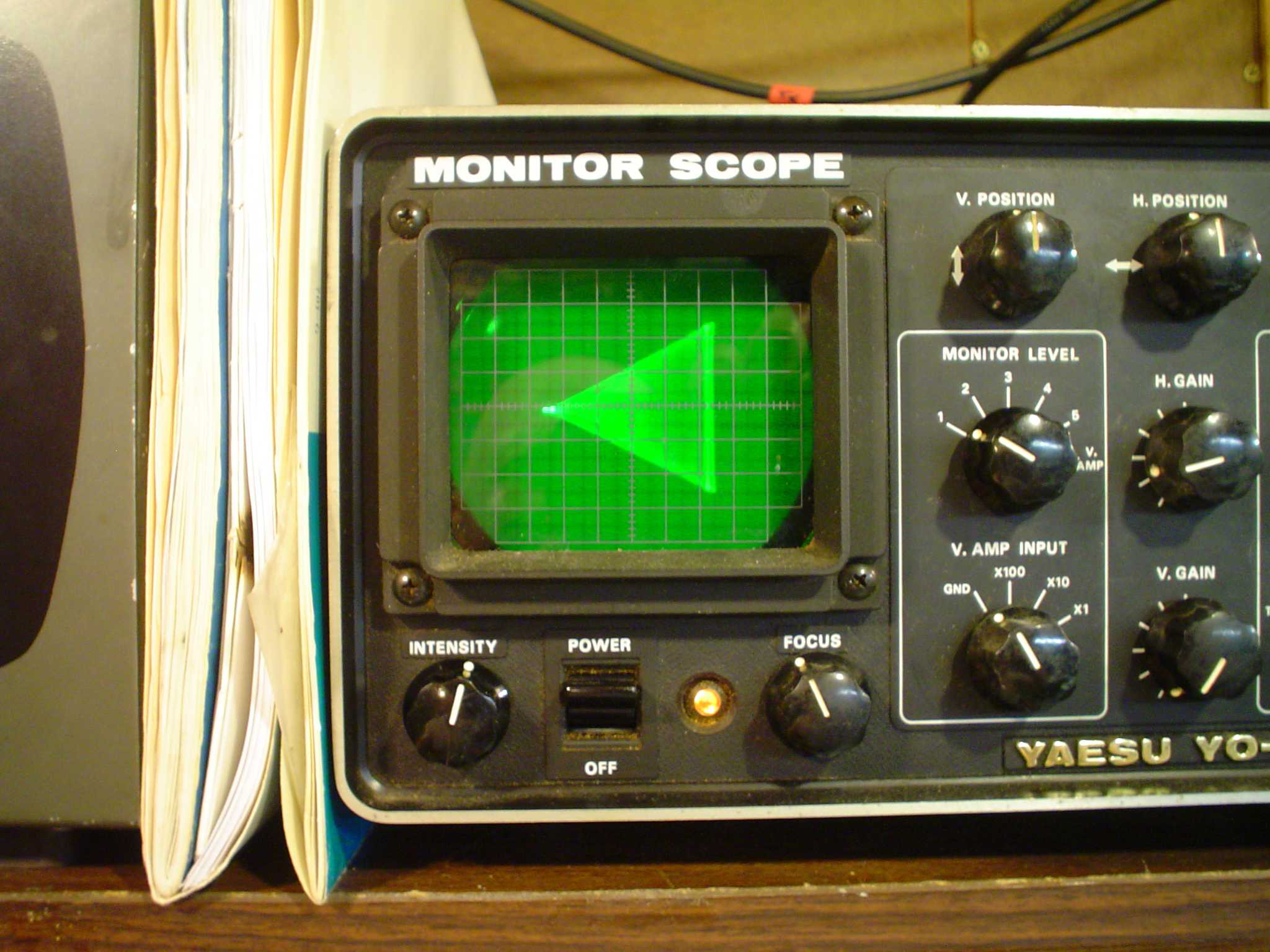
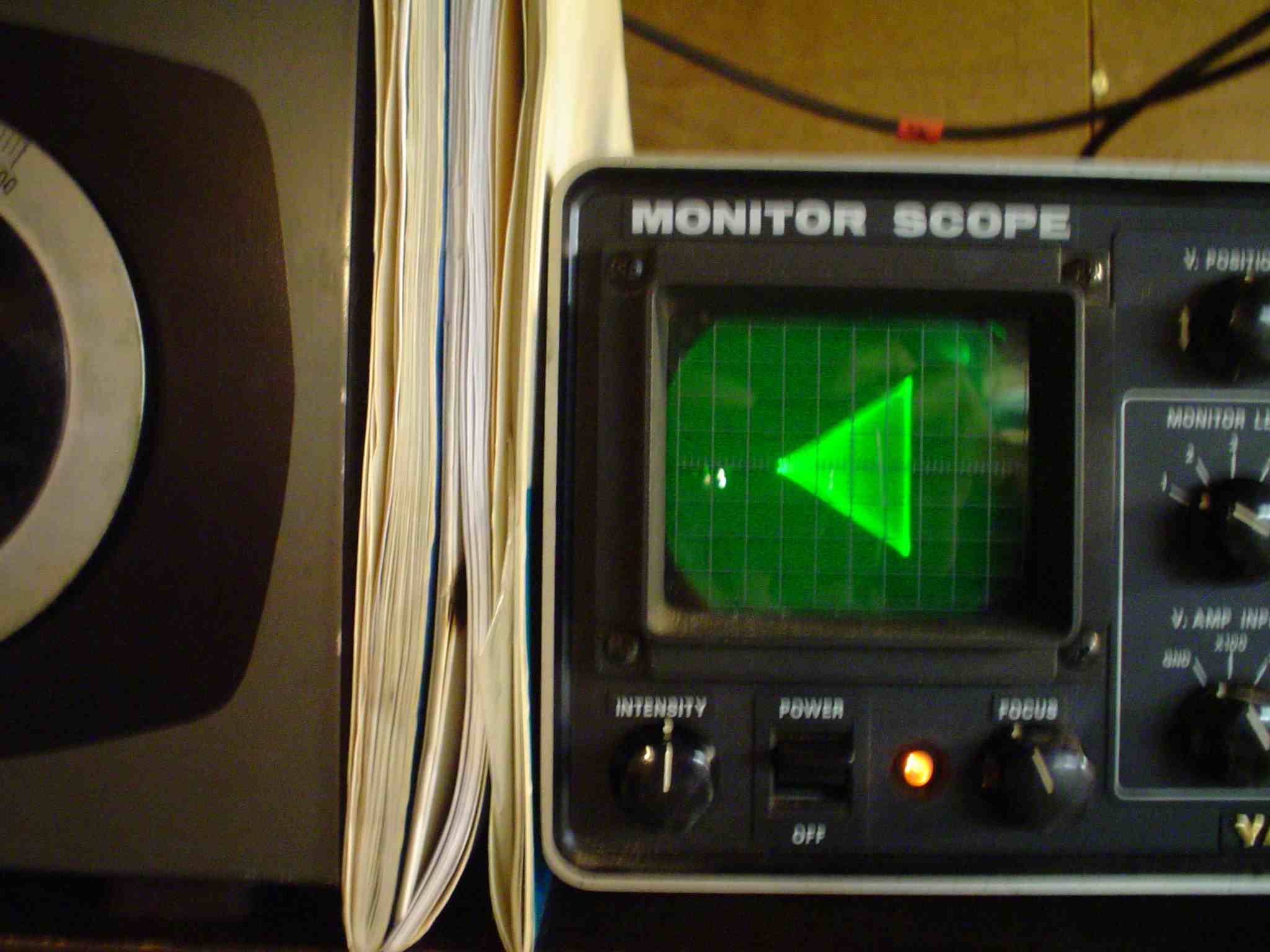
The YO-301 is all solid state, and matches nicely with my FT-950. It will display AF/RF trapezoid and envelope. AF trapezoid is useful for AM modulation linearity display. As you can see, I have two of these. One is set for AF/RF trapezoid on AM, with RF envelope optional. The other is set up with my new Yaesu FT950 and amplifier. It has a built in audio two tone generator. The YO-301 will also display an RF INPUT/RF OUTPUT trapezoid without the use of any external sampler boxes, to test SSB or digital mode linearity.
AF trapezoid is the triangle shaped pattern at the top of this page from my modified Valiant AM transmitter. When using AF trapezoid, do not allow a bright spot to stay on the screen, or you will put a nasty burn in the center of your display tube. In AM it has the RF on the vertical plates, and the modulator audio (reduced to a low level) applied to the horizontal amplifier. If the RF final stage responds to the audio modulation voltage linearly, you get a nice triangle at 100% modulation as shown in my pictures.
RF trapezoid is similar in appearance. For SSB RF trapezoid, you have the amplifier's output RF on the vertical plates, and the exciter's detected RF output to the linear input on the horizontal plates. This requires a special sampling device, which detects the peak waveforms properly to use it for the X-axis as a sort of "sweep" signal. These are commercially available, or you can home brew them from data in the hand books. If the "linear" is truly linear, you get a nice triangle at full output. If there is any curvature, the amplifier may have incorrect bias, incorrect tuning, soft tubes or other problems. Remember non linearity causes splatter on SSB as well as AM.
The envelope display is useful for any mode. In AM it shows the RF hitting the baseline, or 100% negative modulation. In SSB, it shows a similar pattern called the Christmas Tree, when speaking the word "FAAAIIIIIIVE" into the microphone. In SSB, using a two tone input, linearity can be judged from an envelope display.
In DIGITAL MODES, you can see compression of the signal and back down on the power to keep your bandwidth correct for your operating mode. Normally, operators avoid any ALC indication on their transceiver, to avoid distorted broad digital mode signals.
Generally, you can assume that a 100 watt SSB rated transceiver will not do more than 30 watts in any digital mode. This is due to overheating the finals, since it is continuous key down; but it is also due to unacceptable distortion products generated at higher power levels. This is especially true in transceivers that use 13.8 VDC for the collectors of the final transistors. The FT-950 is a class AB1 final, drawing much more resting current, and so is much better on distortion products than many others. The Ten Tec Eagle has a great receiver, but the transmitter had higher than expected IMD output, due to the use of 13.8 VDC finals and some other design considerations. The use of 13.8 VDC finals is made even worse by running the radio off a battery. When the battery starts to discharge, operating voltage gets even lower, and distortion products increase rapidly from there. This is true of radios operated from boats; distortion can increase at lower battery voltages and require starting the engine to charge or reducing the power even lower than 30 watts. Check the QST reviews of your radio. The newer generation of FET output home station transceivers use 50 volts or so and have superior IMD transmit ratings.
Remember, anything you run through a "linear" has distortion products that are the sum of the exciter transceiver IMD and the "linear" amplifier IMD. Start with the best signal you can, before you run it through a linear. Garbage in, even more garbage out.
Can you get by without a monitor scope? Probably, if you watch your ALC, and are using the same brand of linear amp as your exciter. But to really put out a professional grade signal, a monitor scope is a useful tool. Here is some additional information to interpret the patterns displayed on a monitor scope:
http://www.nu9n.com/am.html#introduction
YAESU YO-301 2kW RANGE CALIBRATION
(Update 8/23/2014)
The Yaesu YO-301 scope has a bad limitation, but there is a fix for it. In
the manual, and on the back panel, it is specified for 500 Watts MAX. The
lowest range also is so sensitive it will give full display on a 5 Watt CB
radio. This is probably done to accommodate the lower level license classes in Japan, which have very low power privileges.
WARNING LETHAL VOLTAGES ARE INSIDE THIS SCOPE. The accelerating
voltage for the display tube are above 1 KV. Also the transmitter should
never be on the air when making adjustments to the sensitivity capacitor.
Tweak it off the air and try it with both hands outside the box! Then tweak
it again with all circuits cold. Try it till you get it right. Use
insulated adjusters. Do not drop tools or screws into the works of the
scope or you could fry yourself or the scope. Do not work alone on high
voltage equipment. Remember the jelly bread rule made famous by the Peanuts
comic strip, otherwise known in physics circles as the law of selective
gravitation. A slice of bread with jelly and/or peanut butter always falls
jelly side down on the floor. Likewise, a conductive tool always falls out
of your hand into equipment in such a way as to cause maximum damage.
I just acquired a K7DYY full legal limit (1.5KW PEP) AM transmitter as well
as an ALS-1300 Linear for envelope display. Note that with the K7DYY AM rig, there is no way I can easily devise to use the scope in a trapezoidal pattern, but the envelope pattern is definitive in determining the correct level of audio to use. I wanted to use the Yaesu YO-301 with those rigs at higher power levels. What to
do?
The limitation is not caused by the SO-239 connectors. So what's the deal?
E= square root of P times R.
For 50 Ohms 1:1 SWR and 2000 watts, that works out to 316 V.
For higher SWR, its more voltage.
The input coupling capacitor is only rated for 500 volts and is a high
enough value that it couples too much energy into the vertical deflection
plates. If we increase the voltage rating and attenuate the signal,
everything works out nicely.
I used a series connection of three 500 volt silver mica capacitors of
about the same value, 39 or 33 pF to replace the original single capacitor
C211. To provide a better safety margin, it would be better to use 1000
volt capacitors. Ceramic caps would also be OK.
The deflection was still a little too sensitive, so I put a 20 pF trimmer
cap to ground for adjustment. I adjusted this capacitor to produce full 6 division
deflection with full legal limit. The ranges of the switch are now like
this for 4 divisions vertical
deflection:
- 1000 watts was 500 watts
- 400 watts was 100 watts
- 100 watts was 100 watts-I know this looks screwy. They built it that way.
- 50 watts was 15 watts
- 25 watts was 5 watts
This produces more appropriate ranges for QRO while still allowing display
for carrier balance adjustment on vintage rigs.
Remember when you had to periodically adjust the carrier balance on your
SB102 until the leaking coupling capacitor finally blew out the balanced
modulator diodes?
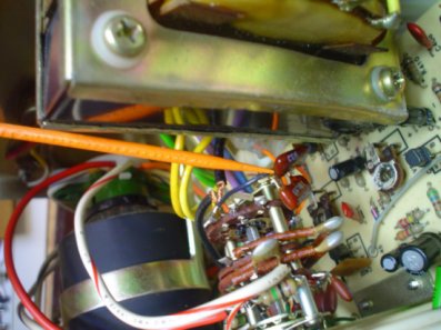
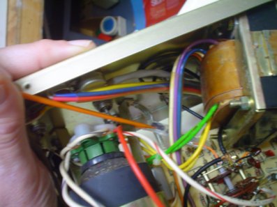
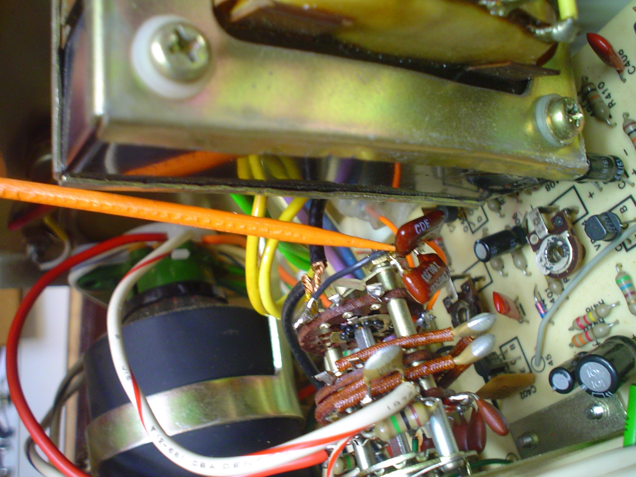
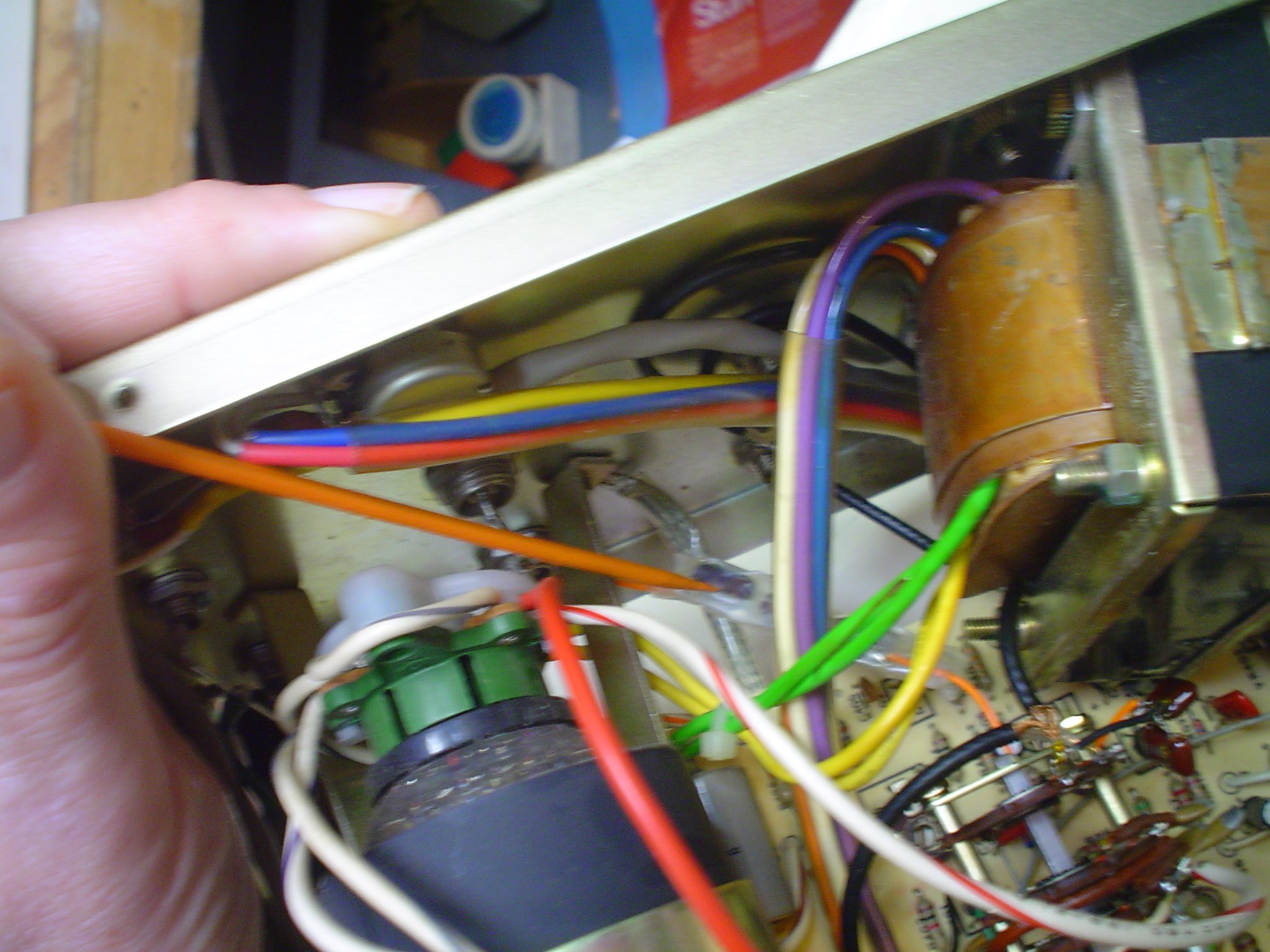
The photos show the C211 that needs to be upgraded. I had fixed capacitors
shown in the other photo, but they did not work out. I put the trimmer on
the monitor level switch as shown by the orange pointer. ROUTE THE C211
AWAY FROM EVERYTHING ELSE to avoid stray coupling or arcs and sparks. I
used clear Kynar high voltage insulating sleeving over C211.